Framing in the data link layer is a vital side wherever a difficulty is often highlighted to form a sense of the events. It will regulate the audience’s perception and additionally the acceptance of a specific meaning. As media plays a specific role in people’s perceptions, negative framing can produce a huge impact on individuals.
:::
:::section{.main}
What is Framing in a Data Link Layer?
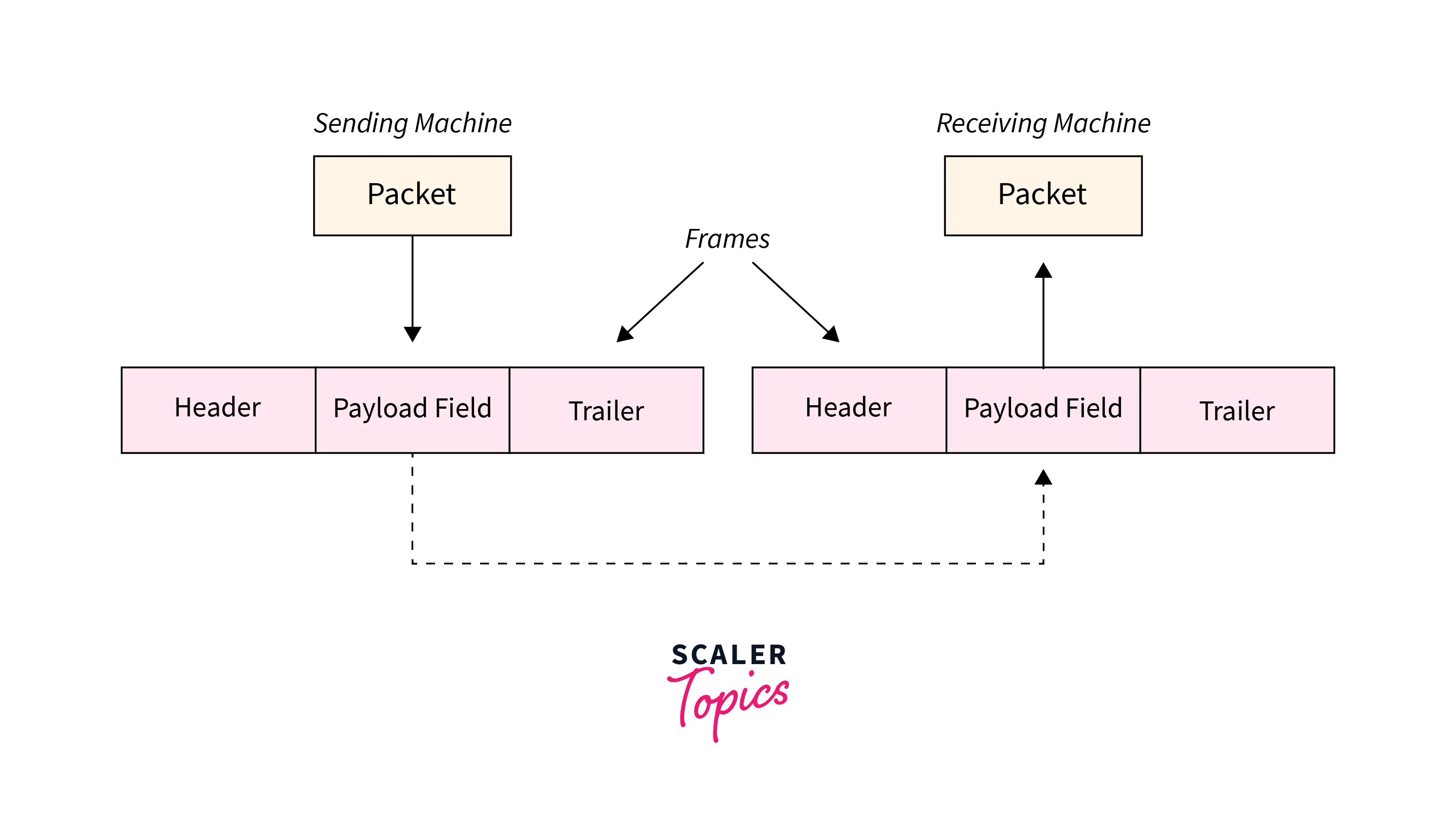
Frames are the units of digital transmission, notably in Framing in Computer networks and telecommunications. Frames are akin to the packets of energy known as photons in the case of sunshine energy. The frame is unendingly utilized in the Time Division Multiplexing method.
Framing may be a point-to-point affiliation between 2 computers or devices consisting of a wire within which knowledge is transmitted as a stream of bits. However, these bits should be framed into discernible blocks of data. Framing may be an operation of the info link layer. It provides the simplest way for a sender to transmit a collection of bits that are important to the receiver. Ethernet, token ring, frame relay, and alternative electrical circuit layer technologies have their own frame structures. Frames have headers that contain data like error-checking codes.
:::
:::section{.main}
Part of a Frame
- Header: It consists of the frame’s source and destination address. A frame header holds the destination address, the supply address, and 3 management fields kind, seq, and ack helping the subsequent purposes:
- kind: This field expresses whether the frame could be an information frame, or it’s used for management functions like error and flow management or link management, etc.
- Seq: This holds the sequence variation of the frame for transcription of out–of–sequence frames and causing acknowledgments by the receiver.
- Ack: This contains the acknowledgment variety of some frames, significantly once piggybacking is employed.
- Payload: It contains the message to be delivered. It contains the particular message or data that the sender desires to transmit to the destination machine. It contains the particular message or data that the sender desires to transmit to the destination machine
- Trailer: It contains the error detection and correction bits.
- Flag: It contains the points to the starting and the ending of the frame.
:::
:::section{.main}
Problems in Framing
Locating at the beginning of the frame: When a frame is transmitted, each station should be ready to notice it. The station detects frames by searching for a special sequence of bits that marks the start of the frame which is. SFD (Starting Frame Delimiter).
How will the station notice a frame: Each station listens to the link for the SFD pattern through a sequential circuit. If SFD is detected, the sequential circuit alerts the station. The station checks the destination address to just accept or refuse the frame.
Locating end of frame: Once to prevent reading the frame.
For example, the communication device sends a hundred bits of information, out of which fifty bits belong to the border one. The receiving device receives all the bits. However, can the receiver understand that up to fifty bits belong to the frame?
Solution: Some protocols square measure outlined between the devices before starting with the communication and knowledge exchange. Let each device agree that the frames begin and finish are 11011 (added with the header and trailer). The frame received by the receiving device can seem like this 1101101101101011011.
If you notice rigorously, there’s another drawback: the frame that’s received contains a region that resembles the beginning and also the finish of frame 1101101101101011011. Hence, the receiver can think about solely these bits 1101101011011,i.e., before the resembling half won’t be thought of as a region of the frame. This can be called a Framing Error. To grasp the solutions to this drawback, we tend to initially learn the categories of framing.
Types of Framing in Data Link Layer
There are two types of framing in the data link layer. The frame can be of fastened or variable size. founded on the size, the following are the types of framing in data link layers in computer networks,
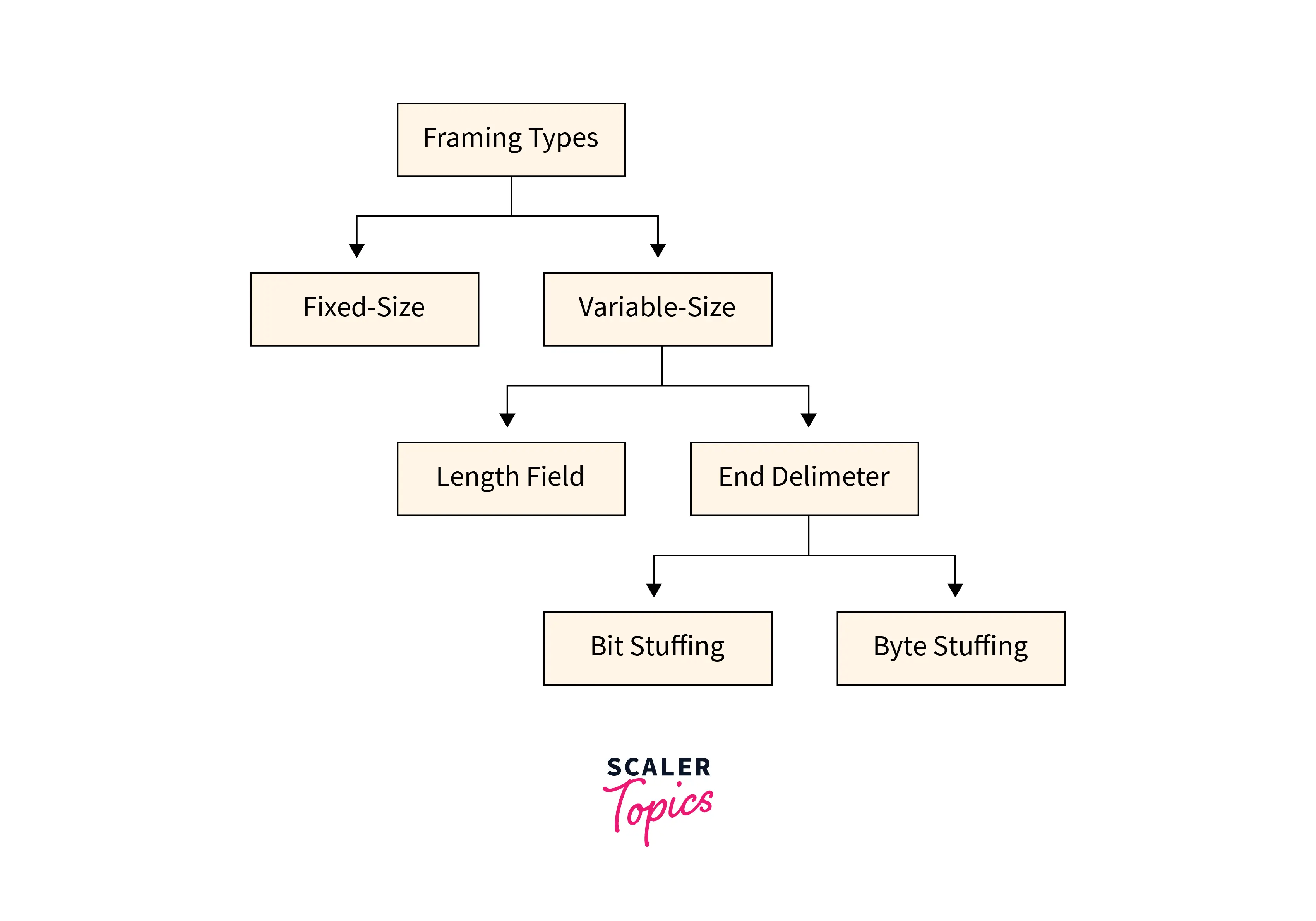
1. Fixed Size Framing
In this Fixed-size framing, the size of the frame is always fixed that’s why frame length acts as the delimiter of the frame. And it also doesn’t require additional boundaries to identify the start and end of the frame.
For example- This kind of framing in the Data Link Layer is used in ATMs and wide area networks(WAN). They use frames of fastened size known as cells.
2. Variable Size Framing
The size of the frame is variable during this form of framing. In variable-size framing, we are in need of a way to outline the tip of the frame and also the starting of the succeeding frame. This can be utilized in local area networks(LAN).
There are 2 different methods to define the frame boundaries, such as length field and finish decimeters.
Length field–To confirm the length of the field, a length field is used. It is utilized in Ethernet (1EEE 802.3).
End Delimeter–To confirm the size of the frame, a pattern is worn as a delimiter. This methodology is worn in the token ring. In short, it is referred to as ED. Two different methods are used to avoid this condition if the pattern happens within the message.
Character Oriented Approach
Bit Oriented Approach
Framing Approaches in Computer Network
Talking about Framing Approaches in computer networking, there are three 3-different kind of approaches to Framing in the Data link layer:
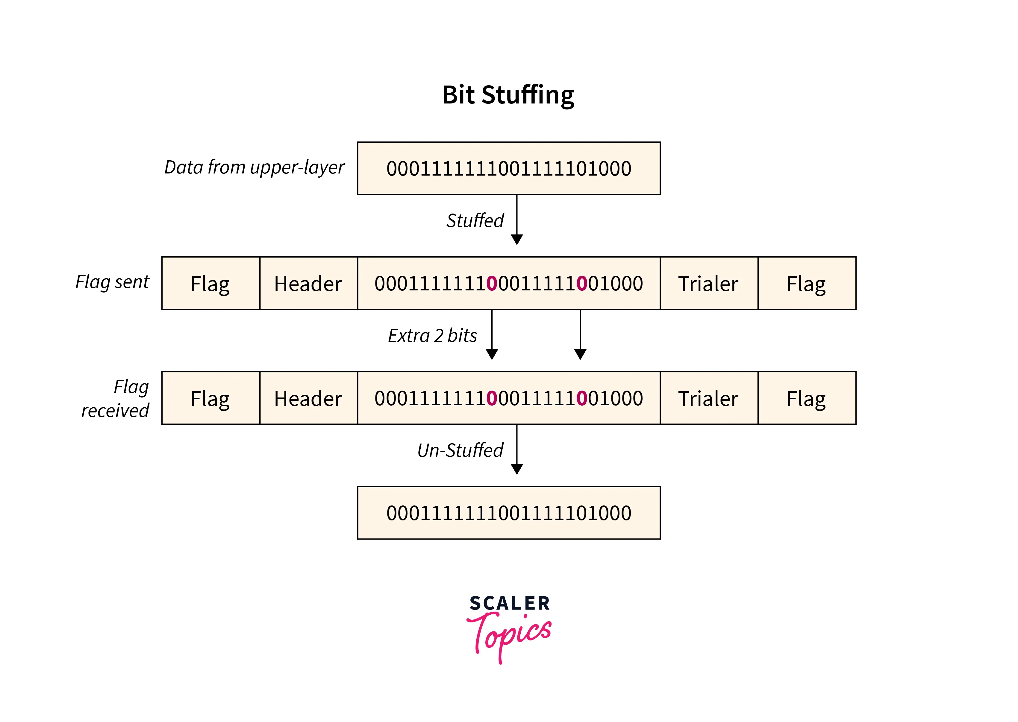
1. Bit-Oriented Framing
Most protocols use a special 8-bit pattern flag 01111110 as a result of the delimiter to stipulate the beginning and so the end of the frame. Bit stuffing is completed at the sender end and bit removal at the receiver end.
If we have a tendency to get a zero(0) after 5 1s. we have a tendency to tend to still stuff a zero(0). The receiver will remove the zero. Bit stuffing is in addition said as bit stuffing.
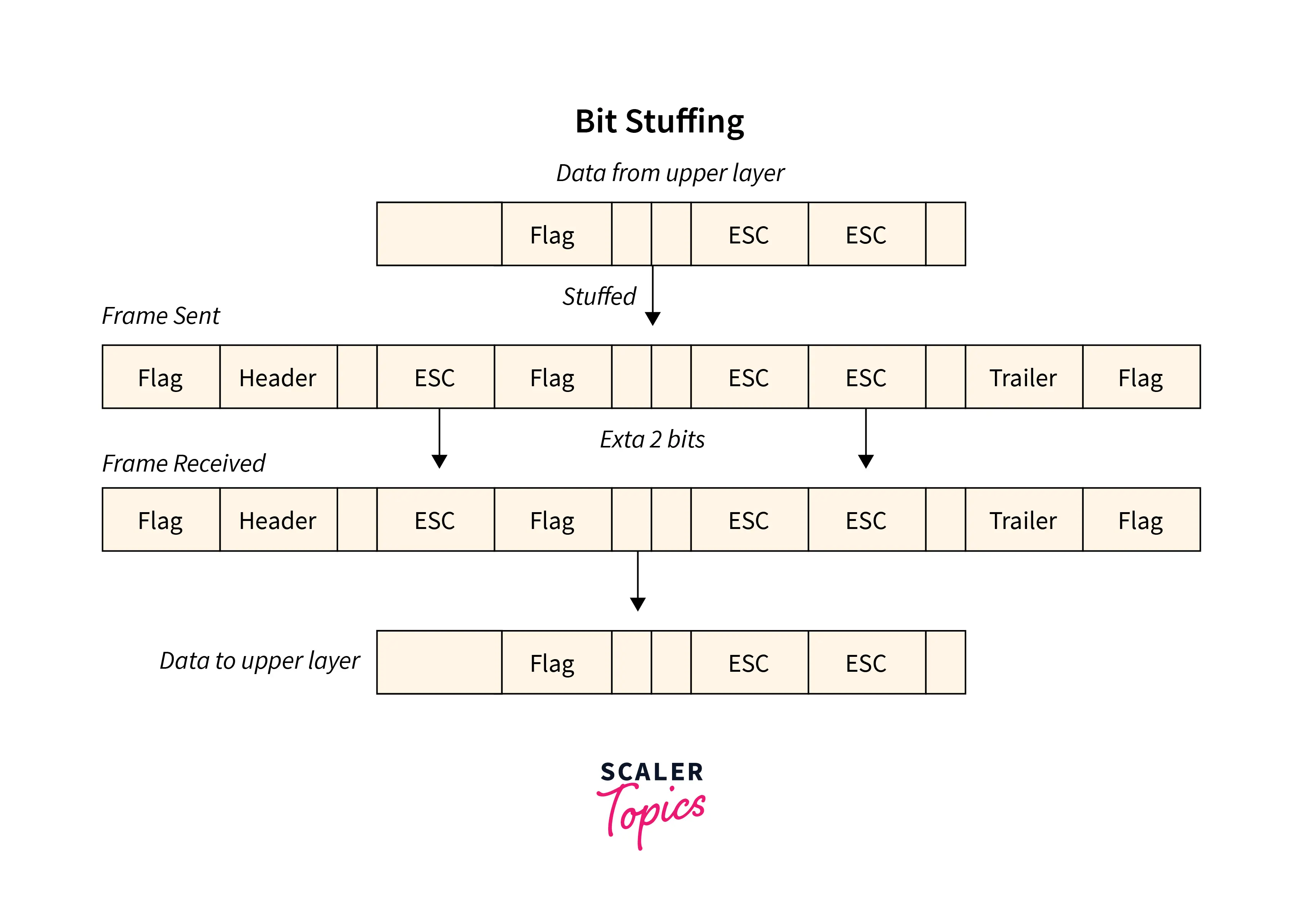
2. Byte-Oriented Framing
Byte stuffing is one of the methods of adding an additional byte once there is a flag or escape character within the text. Take an illustration of byte stuffing as appears in the given diagram.
The sender sends the frame by adding three additional ESC bits and therefore the destination machine receives the frame and it removes the extra bits to convert the frame into an identical message.
Binary Synchronous Communication Protocol (BISYNC)This is a lookout approach. The frame format outlined is given in the below figure, besides the bits.
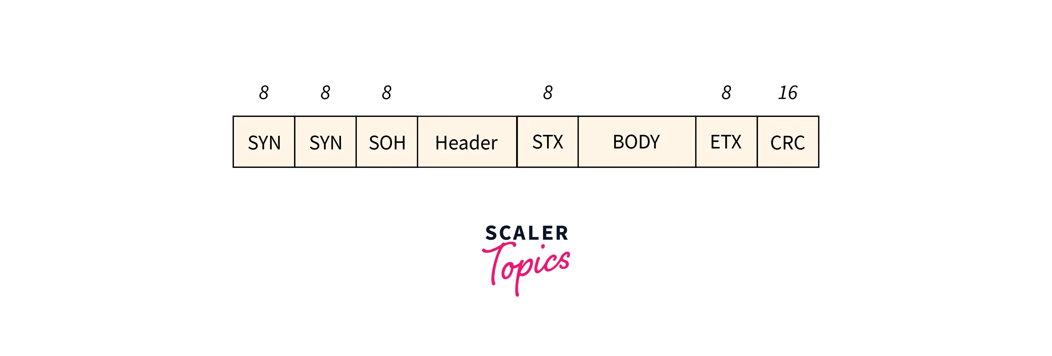
SYN: The Special starting character(SYN),
SOH: The Start of the Header(SOH),
STX: The start of text character(STX),
ETX: The end of text character(ETX)
The STX and ETX look after the data part of the portion. To circumvent the framing in data link layer error problem in this approach, we have introduced Byte Stuffing. This can be used once the frames comprise characters. A byte is stuffed within the message to differentiate from the delimiter.
- Digital Data Communication Message Protocol (DDCMP):
A new count field is introduced during this protocol. The frame format outlined is given in the below figure, in conjunction with the bits.
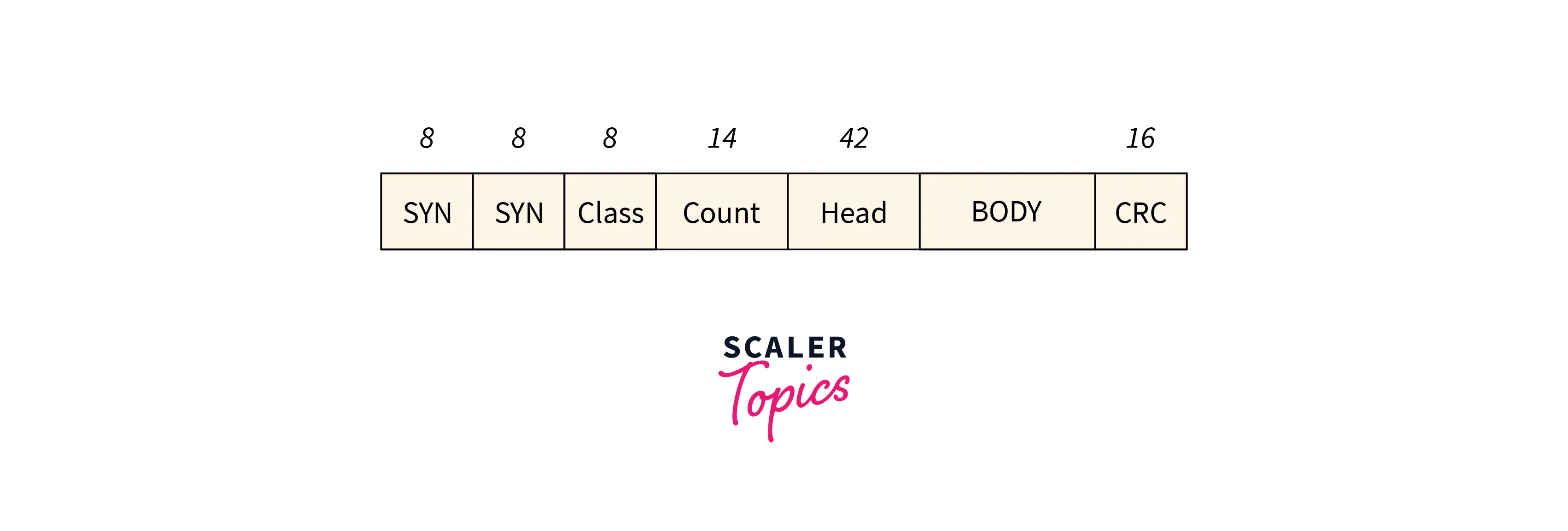
One risk with this approach is that if transmission error corrupts the count field, then the tip of the frame won’t be detected by the receiver properly.
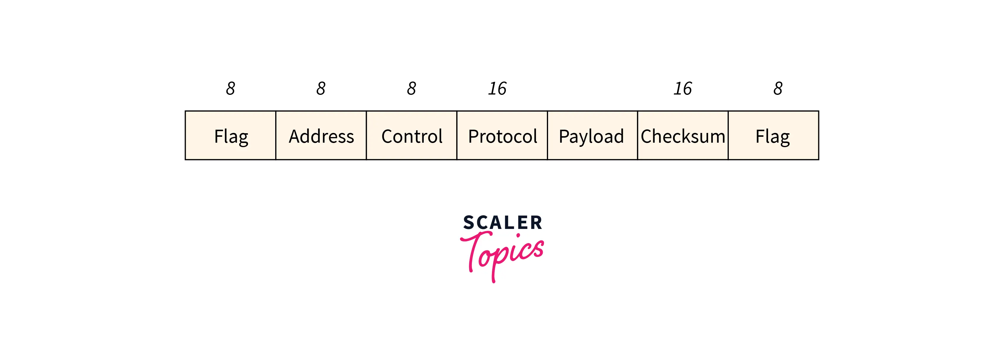
- Point-to-Point Protocol(PPP):
It is an information link layer protocol. It’s a large space network protocol that runs over network links. This protocol is especially employed in broadband communication that deals with high speed and significant hundreds. The frame format outlined is given within the below figure, at the side of the bits.
The bit design of the flag is 01111110.
The address field is set to about 11111111 just in case of broadcast.
The control value is set to be a sustained value of 11000000.
The protocol includes one or two bytes that outline the type of data within the payload section.
The payload carries the data. The topmost length of the particular field is 1500 bytes.
The checksum field is worn for error detection.
3. Clock Based Framing
This framing in the data link layer is basically used for Optical Networks like SONET. In this approach, a sequence of monotonous pulses maintains an everlasting bit rate and keeps the digital bits oriented within the data stream.
Methods of Framing
There are four different methods of framing as listed below –
1. Character Count
In this given methodology is never worn perhaps is usually needed to count the total range of characters that are available in the frame. This process is often done by manipulating fields in the header. This Character count methodology makes sure that the Framing in the data link layer is at the receiver end regarding the total range of characters maintained, and wherever the frame ends.
It also has its disadvantage conjointly of utilizing this methodology which is, if in any case, the character count is issued or bended by a miscalculation occurring throughout the transmission process, then at the receiver end it may drop synchronization. The receiver’s strength is ineffective in finding or establishing the start of the next frame.
2. Flag Byte with Character Stuffing
The Flag Byte with Character stuffing is additionally called byte stuffing or character-oriented framing which is identified as especially of bit stuffing however byte stuffing truly works on bytes because bit stuffing works on their bits. while in byte stuffing, a particular byte that is primarily called ESC (Escape Character) which has a fixed design is usually attached to the data section of the frame once there is communication that has a matching pattern, especially of the flag byte.
However, the receiver detaches the ESC along with the data which may cause difficulties.
3. Starting and Ending Flags, with Bit Stuffing
Starting and Ending Flags, with Bit Stuffing, is additionally called a bit-oriented framing or bit-oriented approach. In bit stuffing, additional bits come about existence supplementary by framing in computer network protocol creators to data streaming. This is typically the lodging of additional bits within the transmission unit as an easy way to offer and provide communication data and information to the recipient and to stay away from or simply disregard the aspect of unwritten or inessential check sequences.
Simply this is a kind of protocol control that is merely performed to interrupt the bit sample which ends up in communication undergoing out of synchronization.
4. Encoding Violations
Encoding violation is a technique that is used just for framing in computer networks within which encoding on physical medium brings about some kind of repetition which is used in more than one graphical or visual structure to easily encode or represent one variable of information.
Advantages of Framing in Data Link Layer
- Framing in Data links is used incessantly within the method of time-division multiplexing.
- Framing in the data link layer facilitates a type to the sender for transmission of a class of valid bits to a receiver.
- Frames are used continuously in the process of time-division multiplexing.
- It facilitates a form to the sender for transmitting a group of valid bits to a receiver.
- Frames also contain headers that include information such as error-checking codes.
- A-frame relay, token ring, ethernet, and other types of data link layer methods have their frame structures.
- Frames allow the data to be divided into multiple recoverable parts that can be inspected further for corrupt
Conclusion
- Framing in the Data link layer additionally contains headers that embody information like error-checking codes.
- Framing in data link layer relay, token ring, ethernet, and alternative sorts of data link layer ways have their frame structures.
- Framing in the Data link layer enables the information to be divided into multiple recoverable elements that may be inspected for corruption.
- Framing in the Data link layer provides a flow management mechanism that manages the frame flow such that the information congestion does not occur on slow receivers thanks to quick senders.
- Framing in the Data link layer provides valid information transfer services within the layers of the peer network.