The cyclic redundancy check (CRC) is widely used as a data transmission error detection tool in the field of data communication, mostly used in digital networks and storage devices. The data sent by the sender side is sent to the receiver by appending a small check code in the data stream. This check code is generated using a special algorithm. By using the same algorithm, the correctness of the data is calculated at the receiver’s end.
What is a Cyclic Redundancy Check?
Let us try to understand the cyclic redundancy check using a real-life example. Consider a situation where you are sending data to your friend. As you know, the basic functioning of how data is transferred over the internet. The data is transferred in the form of packets. Due to several issues on the internet, the data you send to your friend might get changed or corrupted. Then the file received by your friend will not be the same that you sent.
But how come your friend knows if the received file has some error? For this purpose, we use the Cyclic Redundancy Check method to check whether the message received by the receiver is correct or not.
In other words, a change in bits ( from 0 to 1 or 1 to 0) in transmitted data because of a fault in transmission media leads to incorrect data on the receiver side. To solve this problem, we use a cyclic redundancy check.
Cyclic Redundancy Check for Error Control in Data Link Layer
Here, we will see how we can use this method in the data link layer to detect errors on the receiver side. Also will see the data format that is sent from the sender to the receiver.
Let us say a sender wants to send the data of length M. Now, let’s assume that R is the highest degree of generator polynomial function that generates the CRC bits. Then, the sender sends a total of M+R data bits to the receiver.
Let us see how to generate the CRC bits that are appended to the original data. Given that the data stream is 10110011 and the generator polynomial is x4+x+1x4+x+1.
Steps to Generate Sender Data.
Step 1: Append the R number of 0 bits to the end of the data stream, where R is the highest degree of the polynomial. In our case, the value of R is 4 as the highest degree of the generator polynomial function is 4 (x4+x+1x4+x+1). So, our dividend data will be 10110011 + 0000 = 101100110000. Now, we will perform the division by dividing the input stream with the generator polynomial to generate CRC bits. The divisor in our case will be 10011 (i.e., 1.x4+0.x3+0.x2+1.x+11.x4+0.x3+0.x2+1.x+1).  At each step, we perform an XOR operation between the bits.
Step 2: Now, the remainder is then replaced with the appended R number of 0 bits. The input stream will be changed to 10110011 + 0100 (original input data stream + remainder) = 101100110100. Thus, this data is then transferred over the internet and is received by the receiver. In the next step, the receiver will check whether the received bits are correct or not using the same method that was used in Step 1.
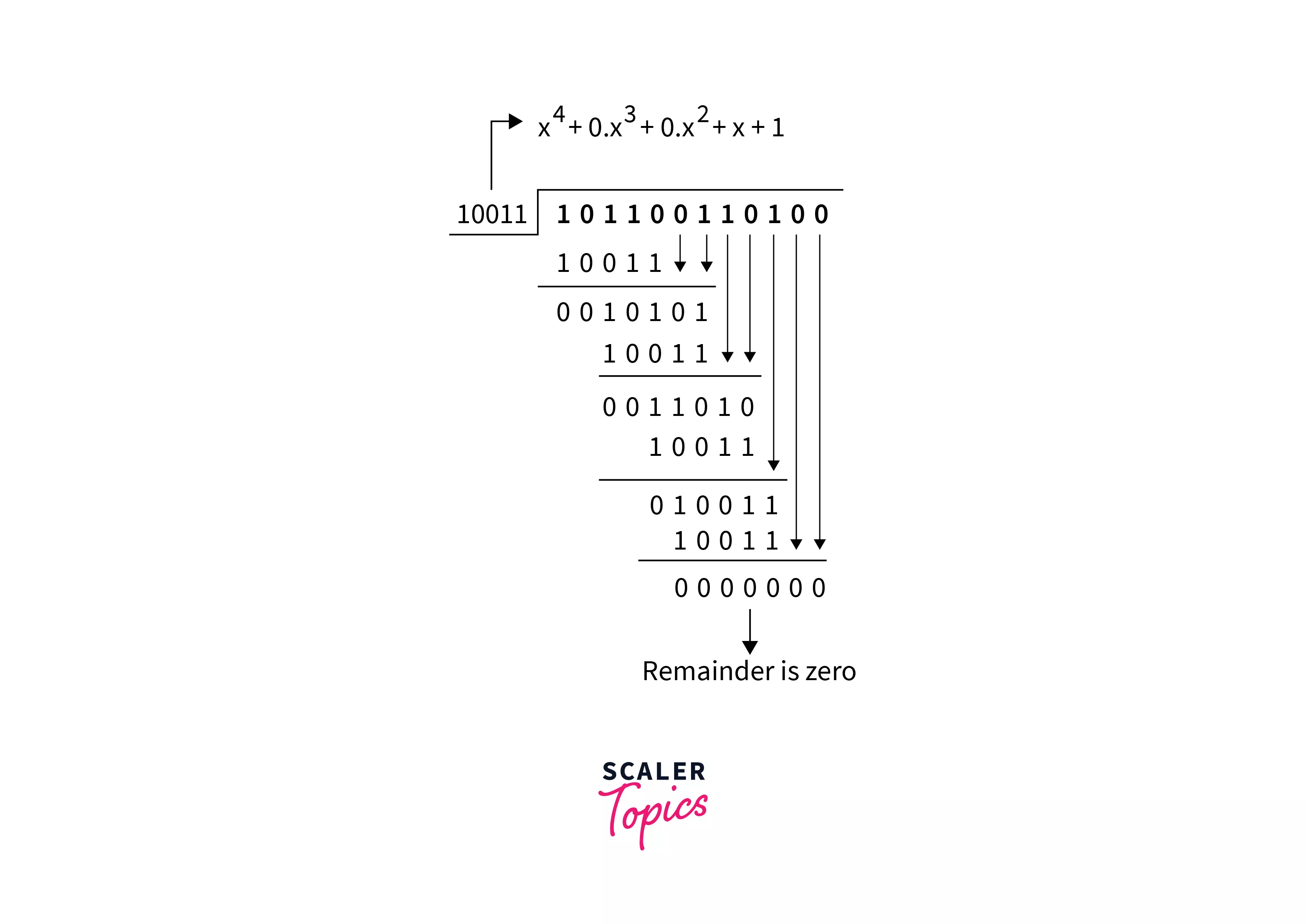
Step 3: In this step, now receiver will perform the following division to check whether the received data is correct or not.  At each step, we perform an XOR operation between the bits. As we can see at the receiver end, the remainder is 0, which means all that transmission of data is done with 100% accuracy. Above is the way to perform the Cyclic Redundancy Check for the error control in the data link layer.
Qualities of CRC
- The CRC should have bits equal to the highest degree of the generator polynomial.
- When you join it to the end of the data unit, you should get a bit sequence that is exactly divisible by the divisor.
- CRC can detect all odd errors, single-bit errors, and burst errors of length equal to the polynomial degree.
CRC Generator and Checker

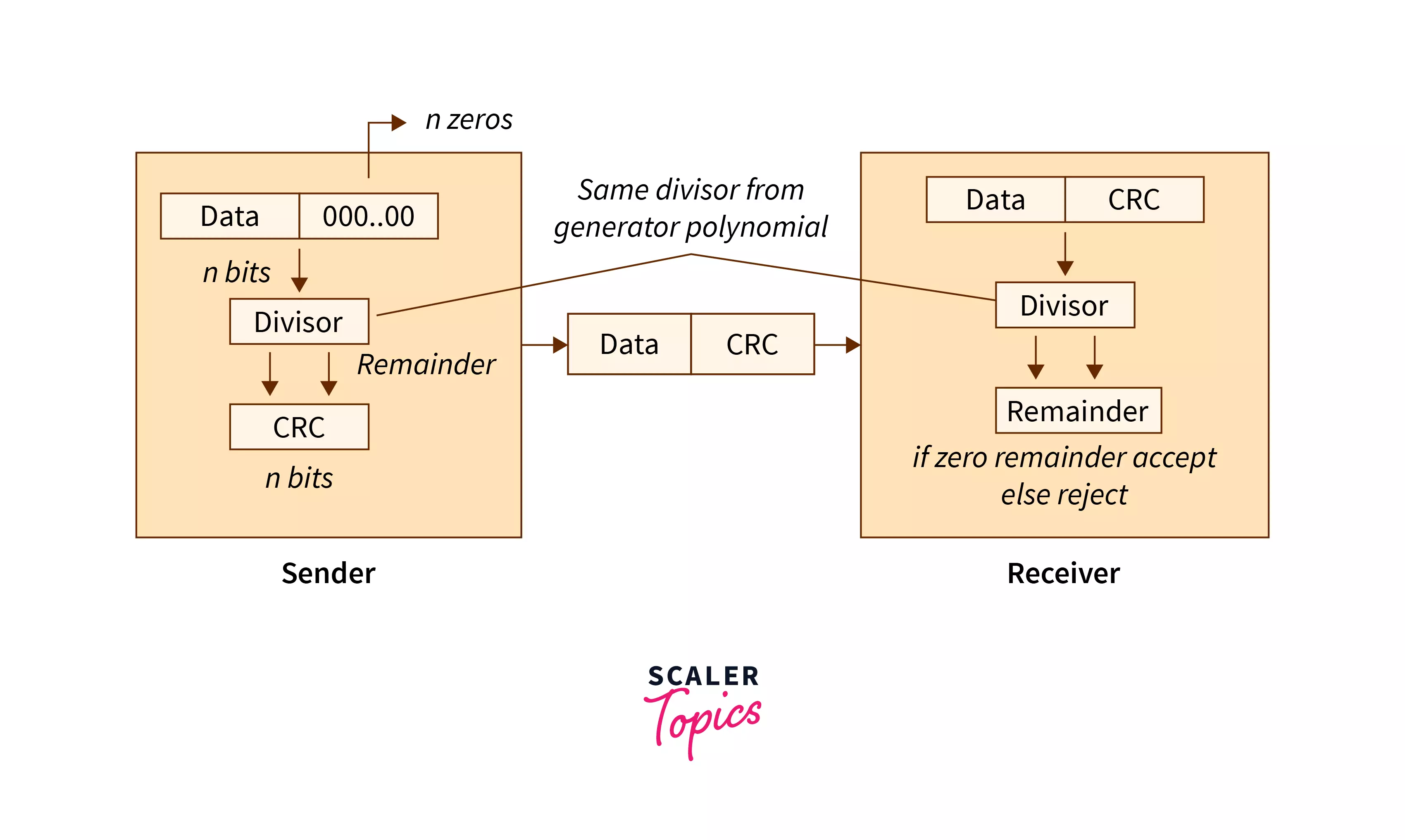
Explanation of the Above Block Diagram
In the sender part, we have appended n bits (all zeroes) to the data part, and then we divide the total data part (data + appended bits) with the divisor (generated from the generator polynomial). Now we get n CRC bits as the remainder. We append the CRC bits to the data part and send it to the receiver.
On the receiver side, we divide the received data with the same divisor. If the receiver gets the remainder value as 0, then the received data is totally correct, or else the received data has some error.
Examples of CRC
Question
Consider the message sender wants to send is 1010001101, and the generator polynomial is x5+x4+x2+1x5+x4+x2+1. Find the message transmitted by the sender. If the receiver receives the message, check if the receiver receives the correct message or not.
Answer
The generator polynomial is x5+x4+x2+1x5+x4+x2+1; therefore, the divisor is 110101. The dividend will become 1010001101 + 0000 (number of bits(n) = highest degree of polynomial). Therefore the dividend = 101000110100000. Now, let us calculate the remainder by performing an XOR operation between bits. 
As we can see the remainder is “01110” (last n bits). Now the sender sends the total data as data + remainder = 1010001101 + 01110 = 101000110101110.
Now, when the receiver receives this data (101000110101110) he will check whether it is the same data that the sender wants to send. The checking will be done by dividing the received data by the divisor generated by the same generator polynomial.
Checking at the receiver’s end.  As we can see the remainder is 0, which means that the receiver receives the correct data.
Conclusion
- Cyclic Redundancy Check is a powerful algorithm that is used for error control in the data link layer.
- The number of 0 bits appended on the sender’s side is equal to the highest number of polynomial degrees.
- If the receiver side gets the remainder as 0 after performing the division, then there is no error in receiving the data at the receiver’s end.
- CRC is used to detect single-bit errors, odd errors, and burst errors of length N (where N is the highest degree of the generator polynomial).