The OSI model stands for Open Systems Interconnection model. The OSI model is also known as the ISO-OSI model as it was developed by ISO (International Organization for Standardization). It is a conceptual reference model that describes the entire flow of information from one computer to the other computer.
The OSI model is a 7-layered model, so it is also known as a 7-layered architecture model. The basic idea behind layered architecture is to divide the design into smaller pieces. Most networks are organized in a series of layers to reduce the design complexity.
What is the OSI Model?
Open System Interconnection (OSI) is a reference model developed in 19841984 by the International Organization for Standardization that specifies how information from one computer’s software application passes through physical media to another computer’s software application.
OSI reference model can be imagined to be a Math assignment of 7 questions divided amongst 7 friends. Instead of one person doing the entire task, we have 7 friends, each taking up one question, thereby reducing the time to complete the task at hand. Each question is independent of the other, and hence each friend can independently answer the questions. Moreover, OSI was intended to serve as a design standard to ensure uninterrupted global communication between computers built on different architectures. Hence, no matter the language each friend understands, be it Spanish or English, and the said friend would be able to understand the question since it is Math.
There are numerous users around the world, and to ensure national and worldwide communication, the ISO developed a conceptual model named the OSI model. We can define the OSI model as a conceptual reference model that describes the entire flow of information from one computer to the other computer. The OSI model is a 7-layered model, so it is also known as a 7-layered architecture model.
Refer to the image below to see the complete representation of the OSI model.
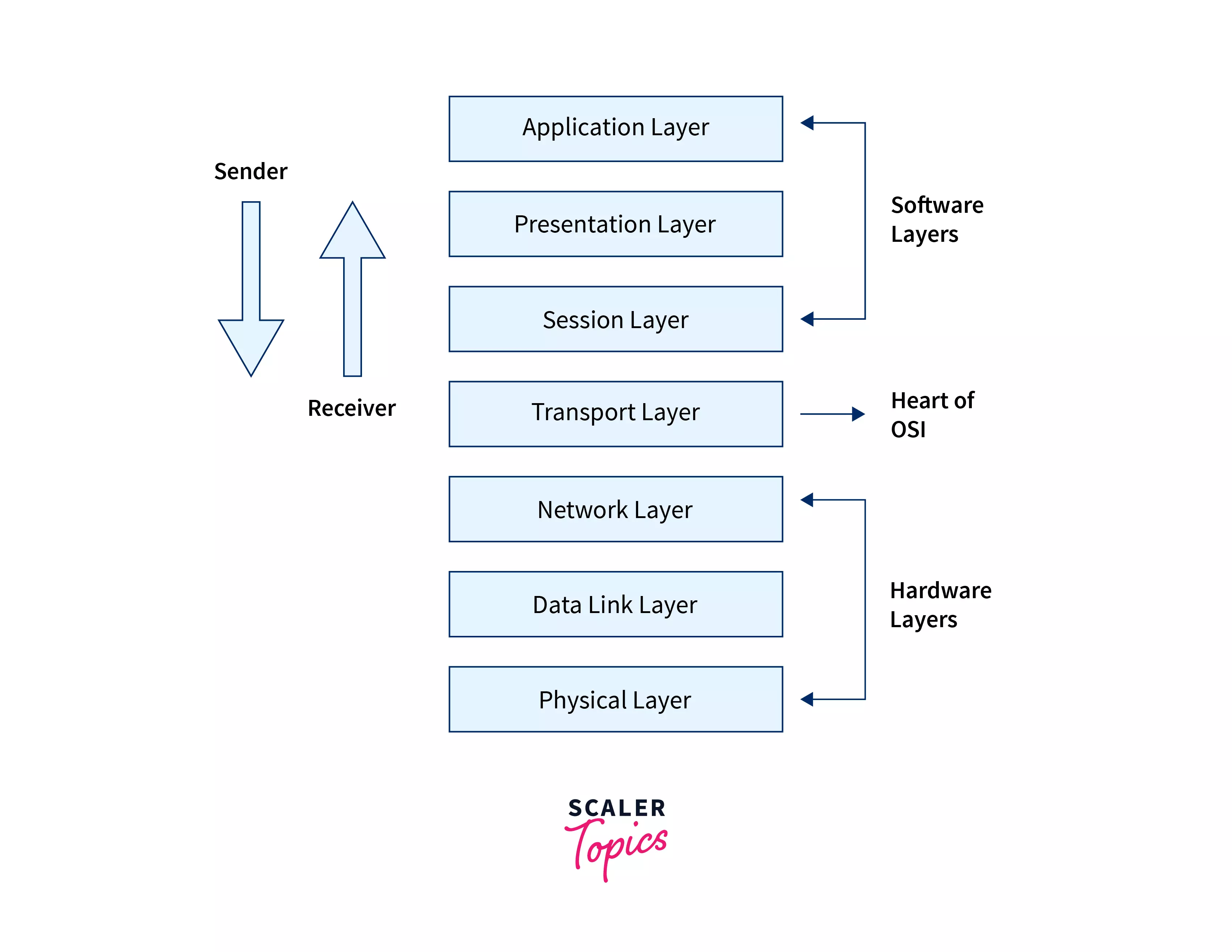
The first three layers are known as the software layer, and the last 3 layers are known as the hardware layer. The transport layer is the heart of the OSI model. The data is sent through the physical layer to the application layer (at the sender’s end). On the other hand, the data is received through the application layer to the physical layer (at the receiver’s end).
The basic idea behind layered architecture is to divide the design into smaller pieces. Most networks are organized in a series of layers to reduce the design complexity. The benefits of this layered division of
the OSI model is discussed below:
- The change in one layer does not affect the other layers.
- The layered architecture reduces the complexity by dividing the task in a manageable way.
- The layered architecture provides abstraction from other layers.
- Due to the abstraction, any layer can be changed independently.
- Each layer can be changed, tested, and analyzed independently.
Note :
Open systems are the systems that are open to communicating and exchanging information over the networks.
The 7 Layers of the OSI Model
As we know, the OSI model is a layered framework for designing network systems that allows communication between all types of computer systems.
Before learning about various layers of the OSI model, let us first know the basic principles of dividing the OSI model :
- The layers should be created only where there is a need for abstraction.
- Each layer of the OSI model should form a well-defined structure.
- Each layer should be defined by keeping in mind the ISO standard protocols.
- The layer’s boundary should be chosen to minimize the information flow across the various interfaces of the layers.
- The number of layers should not be very large (so that the distinct functions are not thrown together), and the number of layers should not be very less (so that features become unwieldy).
The OSI model is divided into 7 layers. Refer to the image provided below to see the basic overview of the various layers of the OSI model.
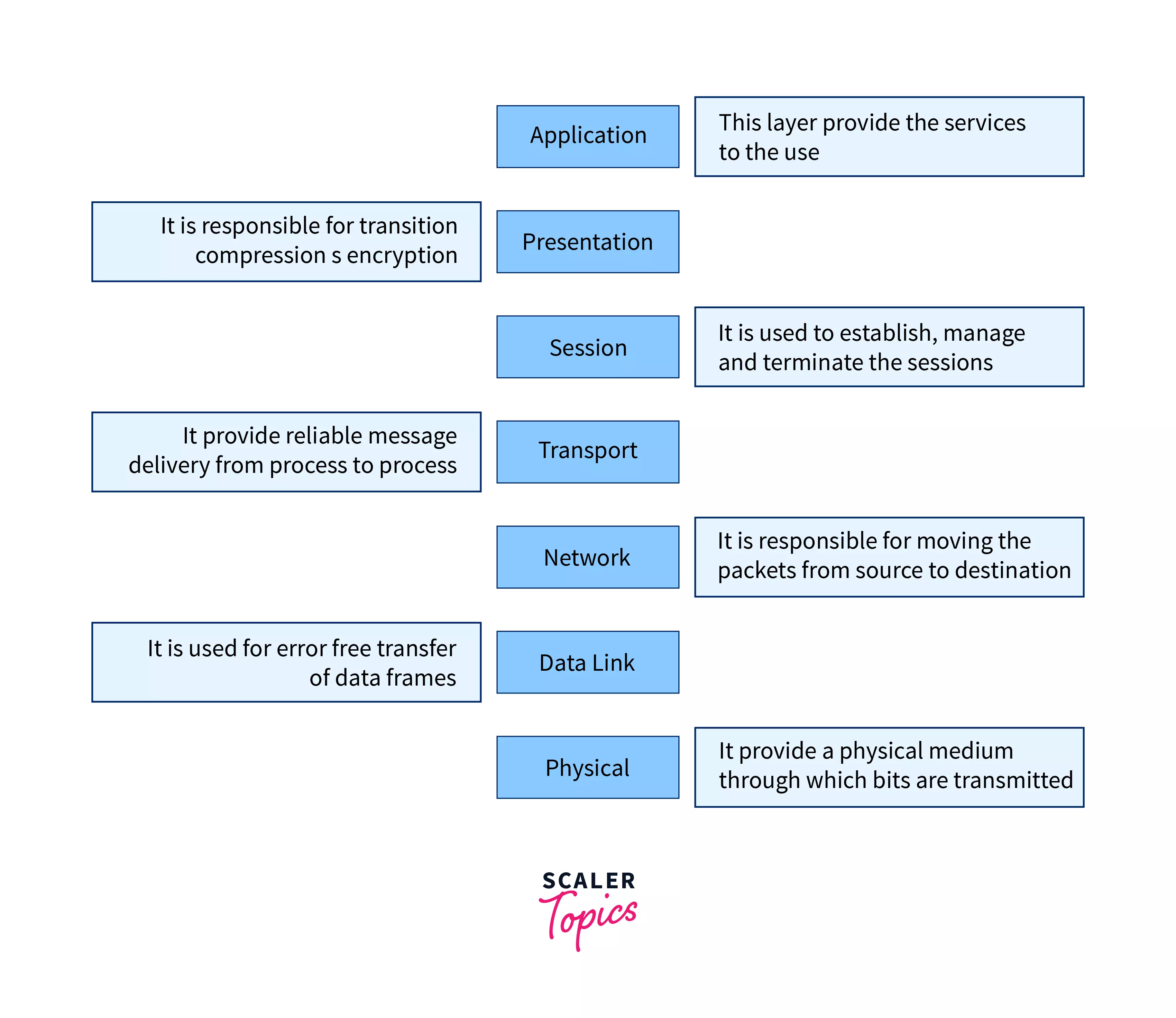
The lower layer is responsible for all the data transfer issues and is also known as the Hardware Layer. The layers present in the lower layer of the OSI Model are :
- Network Layer
- Data Link Layer
- Physical Layer.
The upper layer is responsible for all the application-related issues and is also known as Software Layer. The layers present in the upper layer of the OSI Model are: - Application Layer
- Presentation Layer
- Session Layer
- Transport Layer.
Let us now discuss the various layers of the OSI model in detail.
1. Physical Layer
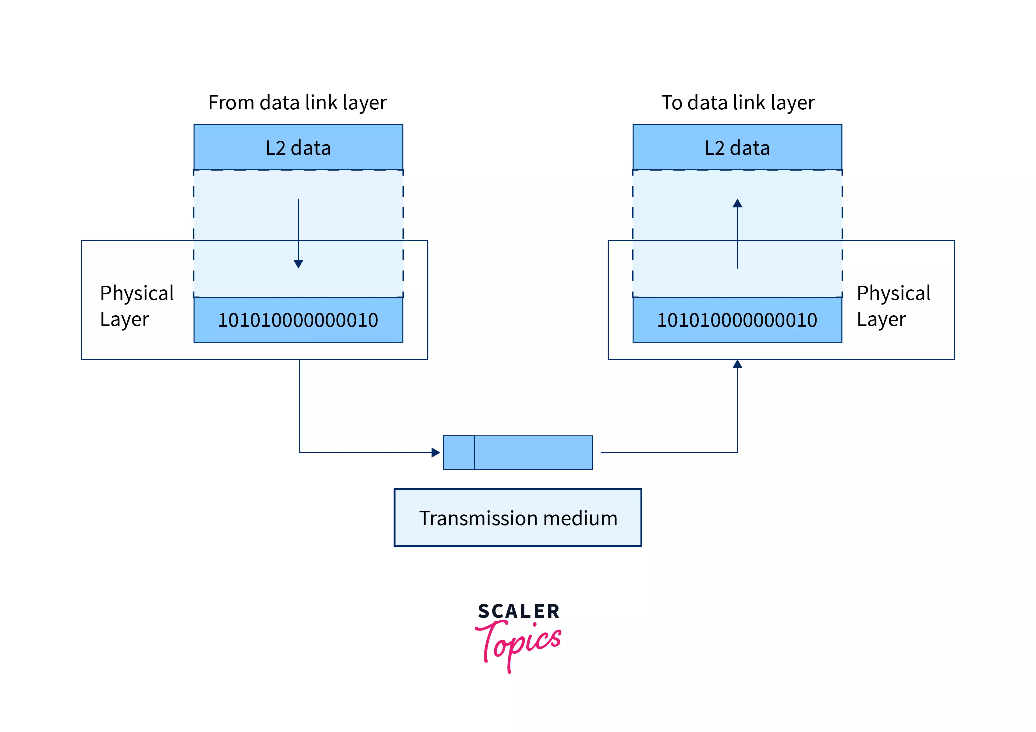
The physical layer coordinates the functions required to transmit the bitstream of data over the physical medium. The physical layer is the lowest layer of the OSI model. The main work of the physical layer of the OSI model is to activate, maintain, and deactivate the physical connection. The physical layer is also responsible for the transmission and reception of the unstructured raw data over the network.
The data in the physical layer consists of a stream of bits. The bits of data must be encoded into the form of signals for transmission. Now, for the transmission, the physical layer sets the voltages, light speed(in the case of fiber optics cable), and data rates (numbers of bits to be transmitted per second).
The functions provided by the physical layer are as follows :
- The physical layer encodes the signals at the sender’s end and decodes the signals at the receiver’s end. It also defines the type of encoding scheme to be used (how 0’s and 1’s are to be changed into signals).
- It deals with the synchronization of the sender and the receiver so that the receiver and the sender are at the same bit level. (Their clocks must be synchronized).
- The physical layer deals with the line configuration i.e. how the devices are connected through a dedicated link.
- It deals with the type of topology to be used for example ring, mesh, bus, star, hybrid, etc. Network topology is the physical and logical arrangement of nodes and connections in a computer network.
- The physical layer also deals with the direction and type of transmission between two or more devices. The mode of transmission can be simplex, half-duplex, and full duplex.
Note :
- Simplex :
communication channel that sends information in only one direction. - Half-duplex :
communication channel that sends information in both directions, but one at a time. - Full-duplex :
communication channel that sends information in both directions on a network at the same time.
Refer to the image below to see the primary transmission of data and working of the physical layer.
The various protocols used in the physical layer are :
- Digital Subscriber Line.
- Integrated Services Digital Network.
- Ethernet, etc.
The various devices used in the physical layer are :
- Network adapters,
- Hubs,
- Cables,
- Repeaters,
- Modem, etc.
2. Data Link Layer
The data link is the second layer of the OSI model, which is used to transmit the error-free frames from one node to the other. If the two computer nodes are on the same networks, then the data link layer provides a connection between the two nodes. The main work of the data link layer is to convert the data into the form of frames (refer to the sub-section below for details about framing).
The functions provided by the physical layer are as follows :
- It provides reliable and efficient communication between two or more devices.
- Framing :
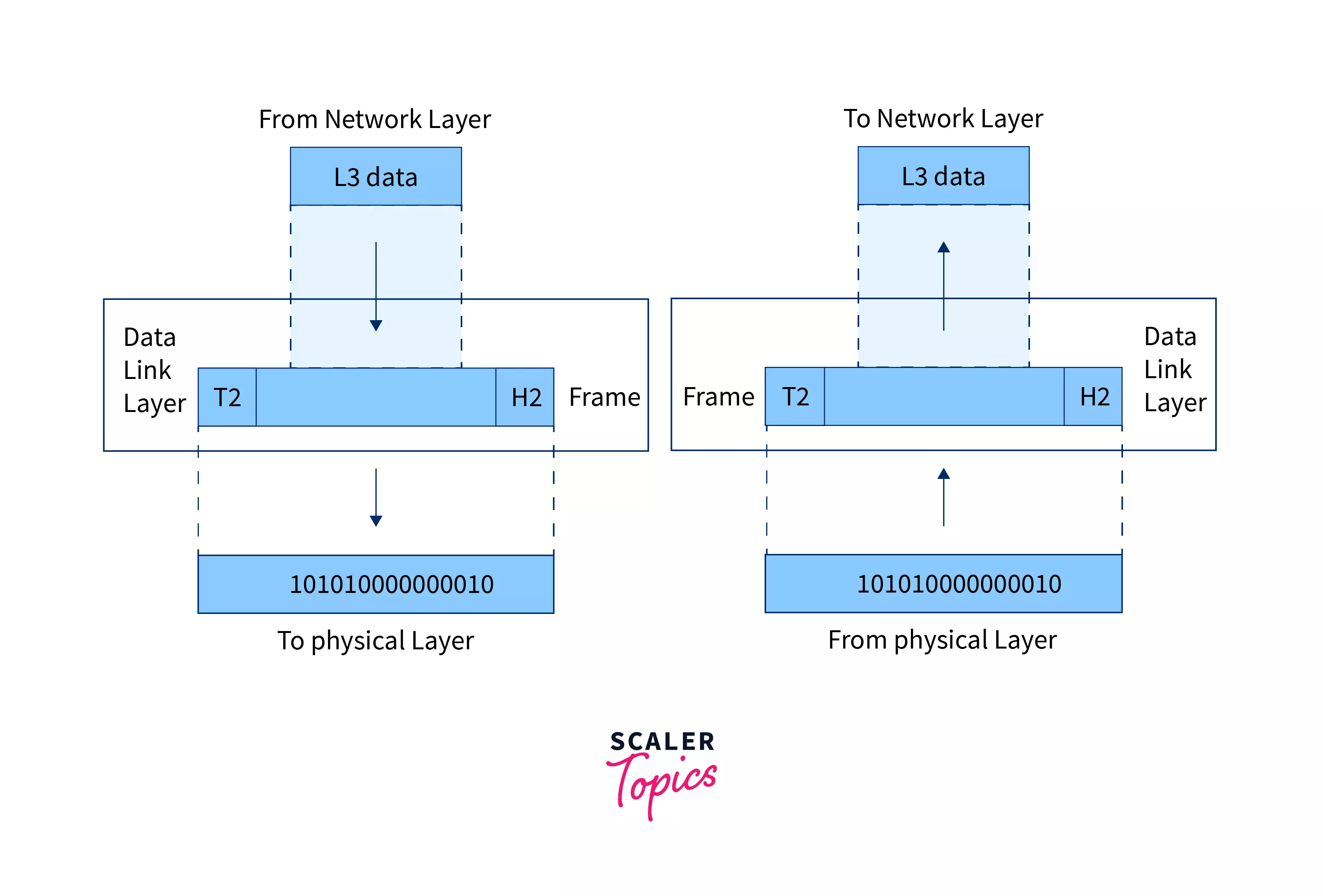
Framing is the technique in which the data is divided into streams of bits (called frames) received from the network layer. Along with the conversion of data into frames, the data link layer adds a header and trailer to the frames. The header (present at the starting of the frame) contains the hardware’s physical address of source and destination. The trailer (present at the end of the frame) contains the error detection and correction bits. - The data link layer also maintains the flow control of data during transmission. Suppose that the rate of data transmission and data absorption varies then there is data loss, so the data link layer maintains the flow control.
- As we have seen above, the data link layer adds the error detection and correction bits at the end of the frames in the form of trailers. These bits are used to detect the errors and then retransmit the damaged or lost data to prevent any kind of duplication.
- It also maintains access control. In situations where two or more devices are connected to the same communication medium then the data link layer protocols determine the device that can transmit the data.
Note :
The physical address is also known as the MAC (media access control) address. The MAC address is a unique address of each computer present on the NIC card.
Refer to the image below to see the primary transmission of data and working of the data link layer.
The various protocols used in this layer are :
- PPP (Point-to-Point Protocol),
- Frame Relay,
- ATM (The asynchronous transfer mode protocol), etc.
The various devices used in this layer are :
- Bridges,
- Switches,
- NIC cards (Network Interface Cards), etc.
3. Network Layer
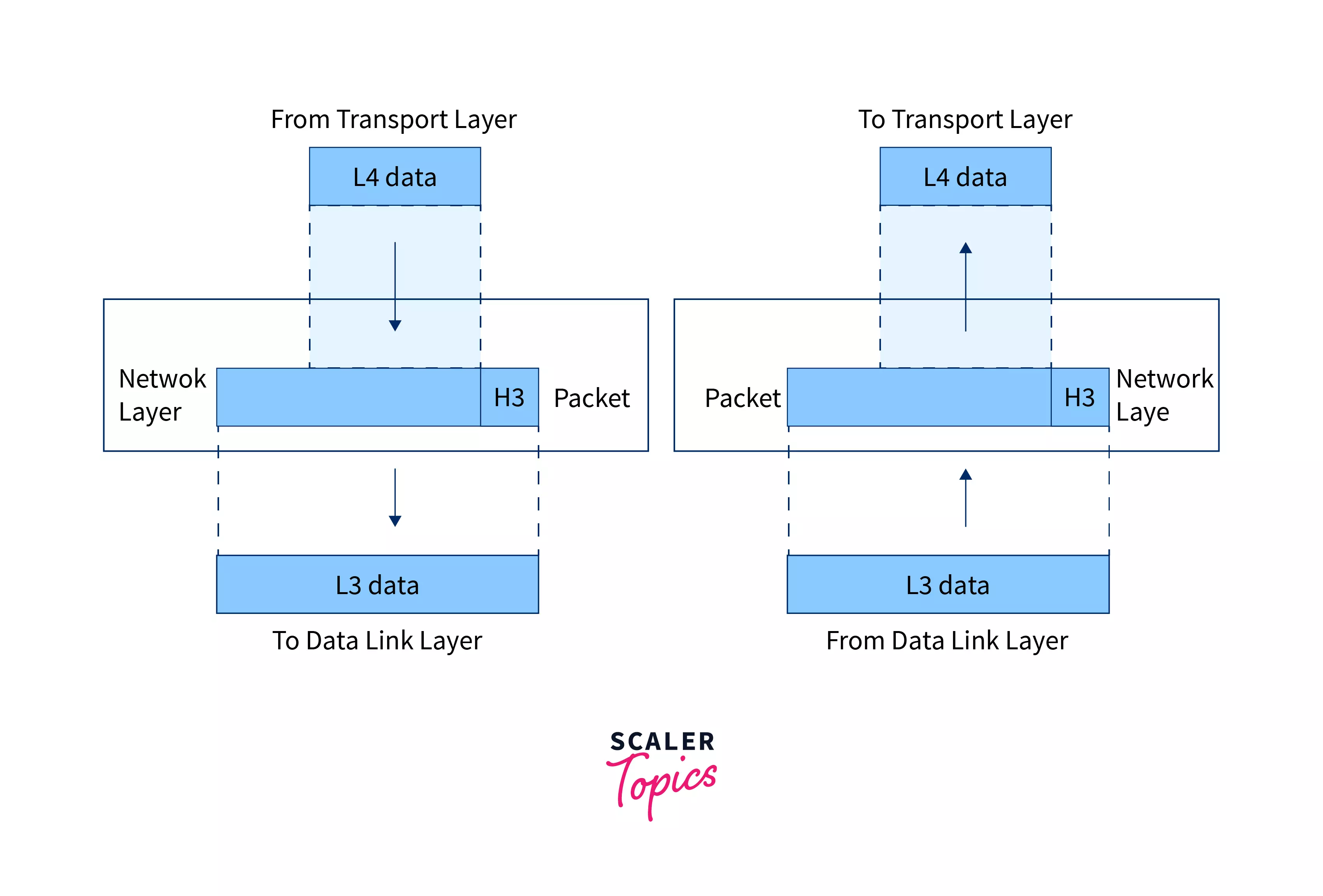
The network layer is the third layer of the OSI model which provides communication between hosts of different networks. The network layer divides the data received from the transport layer in the form of packets. The network layer provides two ways of communication namely – connection-oriented and connectionless.
Note :
- In connection-oriented communication, a communication session is established before any useful data can be transferred.
- In connectionless communication, the data can be transferred without establishing any connection.
The functions provided by the network layer are as follows :
- Logical Addressing :
The network layer adds the logical address i.e. IP address (Internet Protocol address) if the packet crosses the network boundary. It helps in the proper identification of devices on the network. Hence, the network layer adds the source and destination address to the header of the frame. - Routing :
Routing simply means determining the best (optimal) path out of multiple paths from the source to the destination. So the network layer must choose the best routing path for the data to travel. - If many devices are connected to the same router then there is a change of packet drop because a router may not be able to handle all the requests. So, the network layer controls the congestion on the network as well.
Refer to the image below to see the primary transmission of data and working of the network layer.
The various protocols used in this layer are :
- IPv4 (Internet Protocol version 4),
- IPv6 (Internet Protocol version 6),
- ICMP (Internet Control Message Protocol),
- IPSEC ( IP Security),
- ARP (Address Resolution Protocol),
- MPLS (Multiprotocol Label Switching), etc.
The various devices used in this layer are :
- Routers,
- Brouters, etc.
Note :
The network layer does not guarantee the delivery of packets to the destination. There is no reliability guarantee as well.
4. Transport Layer
The transport layer is the fourth layer of the OSI model which is responsible for the process to process delivery of data. The main aim of the transport layer is to maintain the order so that the data must be received in the same sequence as it was sent by the sender. The transport layer provides two types of services namely – connection-oriented and connectionless.
The functions provided by the transport layer are as follows :
- The transport layer maintains the order of data.
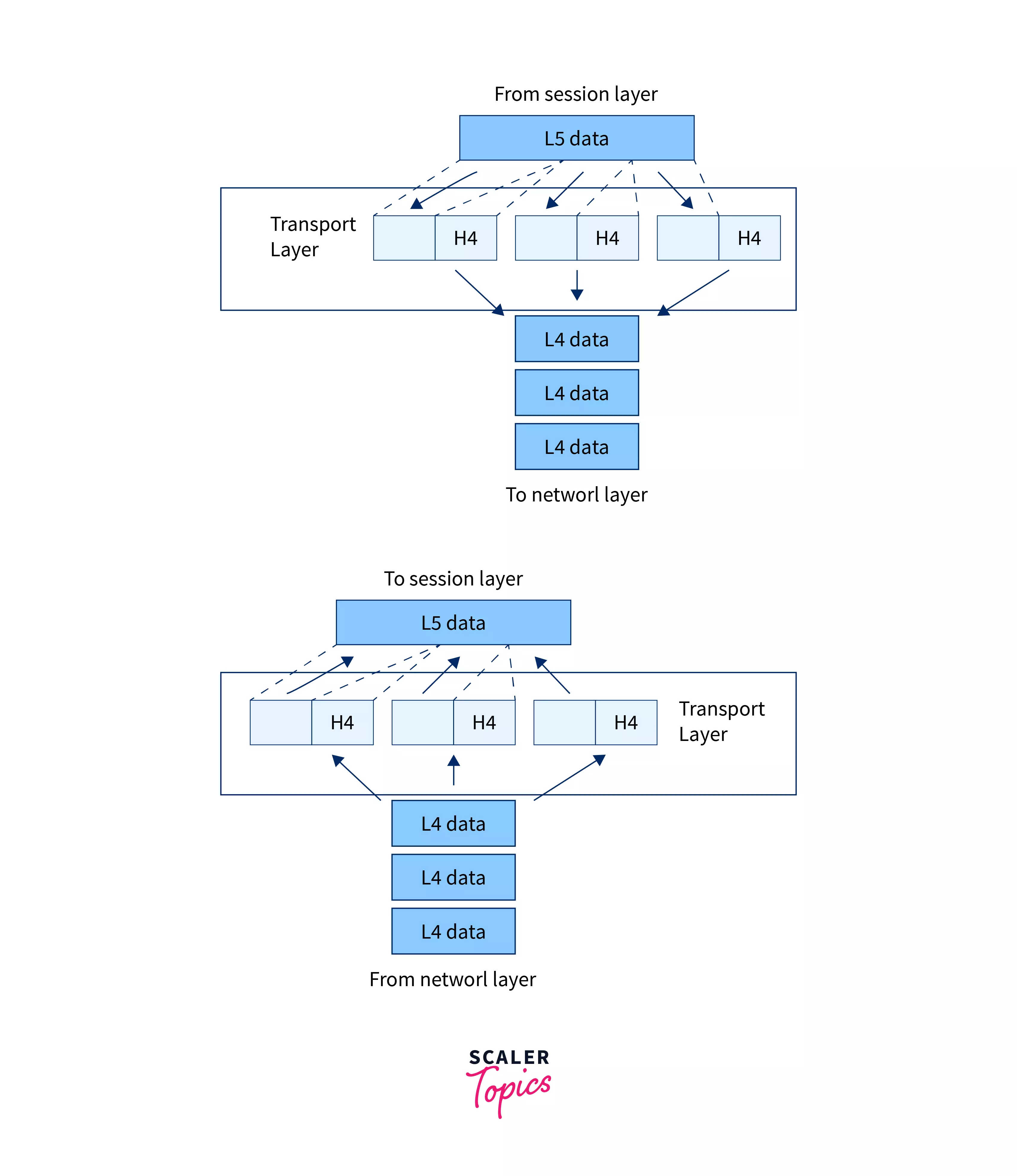
- It receives the data from the upper layer and converts it into smaller parts known as segments.
- One of the major tasks of the transport layer is to add the port addressing (addition of a port number to the header of the data). The port number is added so that the data can be sent to the respective process only.
- The transport layer on the receiver’s end reassembles the segments to form the actual data.
- The transport layer also deals with flow control and error control (discussed in the physical layer section).
Refer to the image below to see the primary transmission of data and working of the transport layer.
The various protocols used in this layer are :
- TCP (Transmission Control Protocol),
- UDP (User Datagram Protocol), etc.
The various devices used in this layer are :
- Segments,
- Load Balancers/Firewalls, etc.
5. Session Layer
The session layer is the fifth layer of the OSI model whose main aim is to establish, manage, and terminate the connection between applications.
There are mainly two functions provided by the session layer, they are as follows :
- The session layer is responsible to create a dialog box which allows two systems to enter into a dialog and transmit the data in either half-duplex or full-duplex mode.
- The session layer is also responsible t adding synchronization bits or checkpoints into the stream of data. These checkpoints help to detect any kind of error that may have occurred during the data transmission. So, if an error has occurred in between the transmission then the re-transmission will take place from the last checkpoint only.
Note :
Half-duplex allows the transmission of signals in both directions but not simultaneously. On the other hand, the full-duplex allows the ion of signals in both directions at the same time.
Refer to the image below to see the primary transmission of data and working of the session layer.
The various protocols used in this layer are :
- PAP (Password Authentication Protocol)
- PPTP (Point-to-Point Tunneling Protocol)
- RPC (Remote Procedure Call Protocol)
- RTCP (Real-time Transport Control Protocol), etc.
The various devices used in this layer are :
- Gateway, etc.
6. Presentation Layer
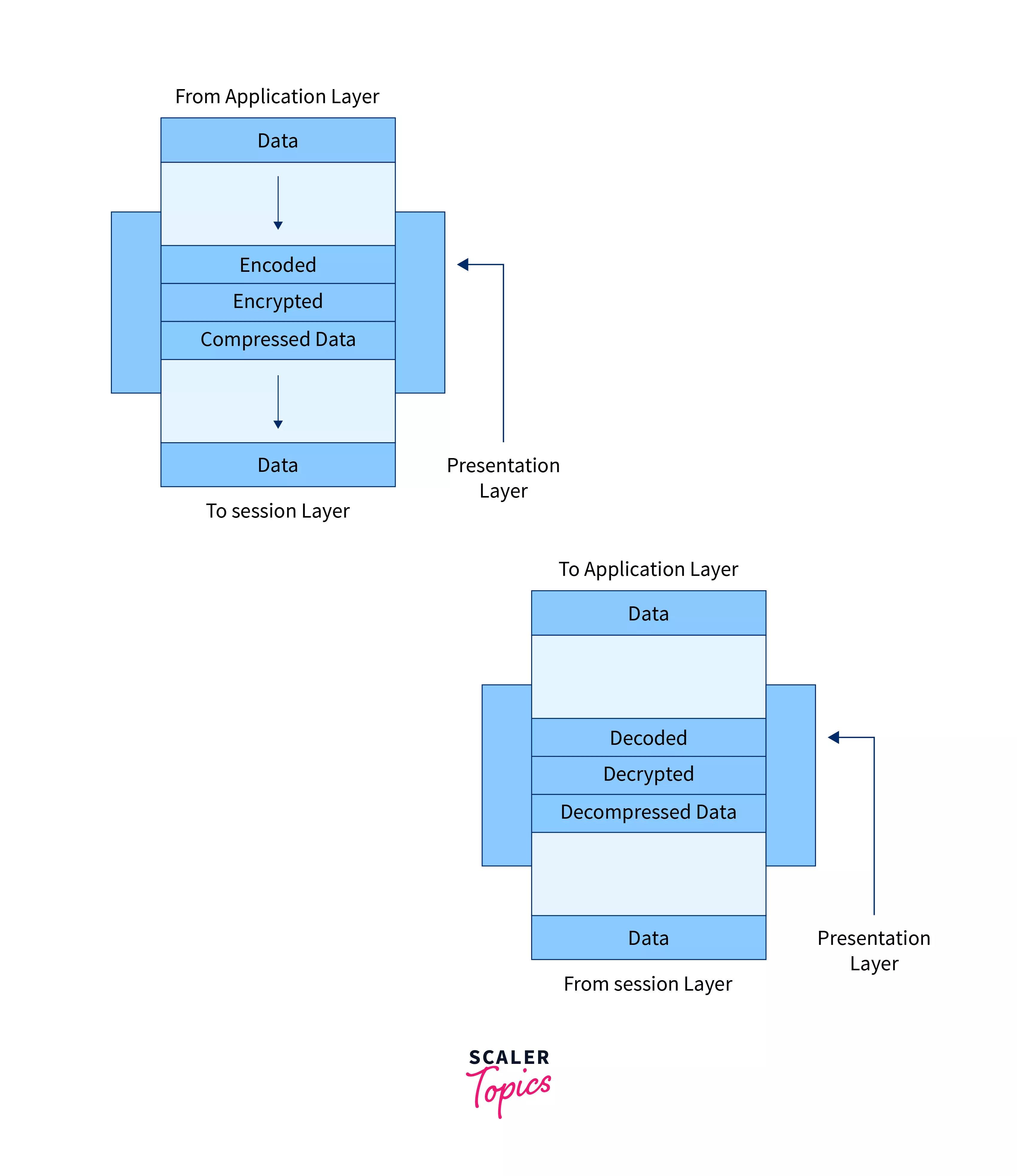
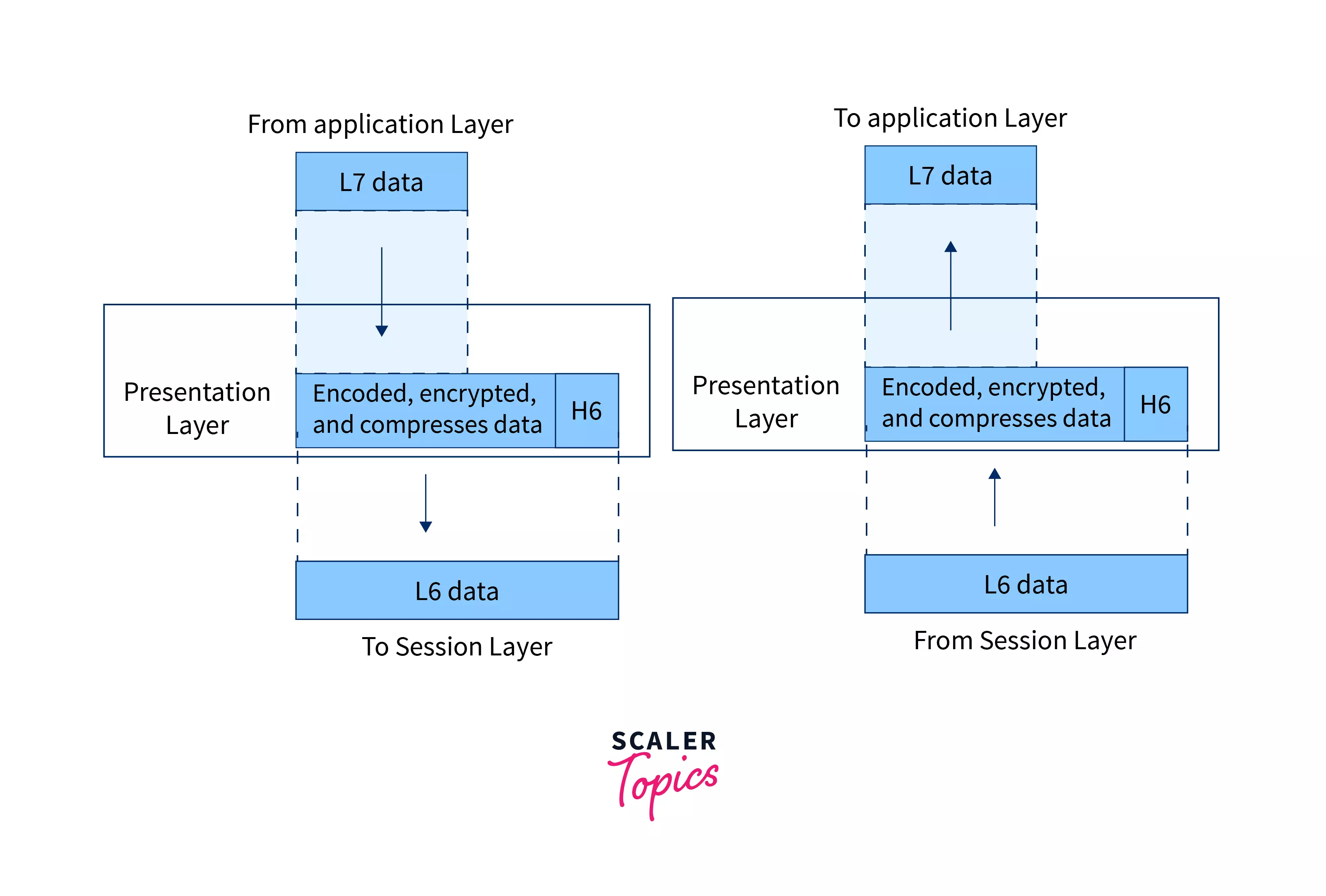
The presentation layer is the sixth layer of the OSI model which mainly concentrates on the syntax and semantics of the information exchanged between the systems. The main aim of the presentation layer is to convert the data from one presentation format to the other format as different applications may use different applications.
There are mainly three functions provided by the presentation layer. They are as follows:
- Since different computer systems use different encoding systems, the presentation layer must translate the data into a computer-dependent format.
- The presentation layer deals with the encryption and decryption of the data so that the data can be transmitted securely.
- The presentation layer also deals with the compression and expansion of the information.
Refer to the image below to see the basic transmission of data and the working of the presentation layer.
The various protocols used in this layer are:
- AFP (Apple Filing Protocol),
- ICA (Independent Computing Architecture),
- Citrix system core protocol,
- LPP (Lightweight Presentation Protocol),
- NCP (NetWare Core Protocol),
- NDR (Network Data Representation),
- Tox protocol, etc.
7. Application Layer
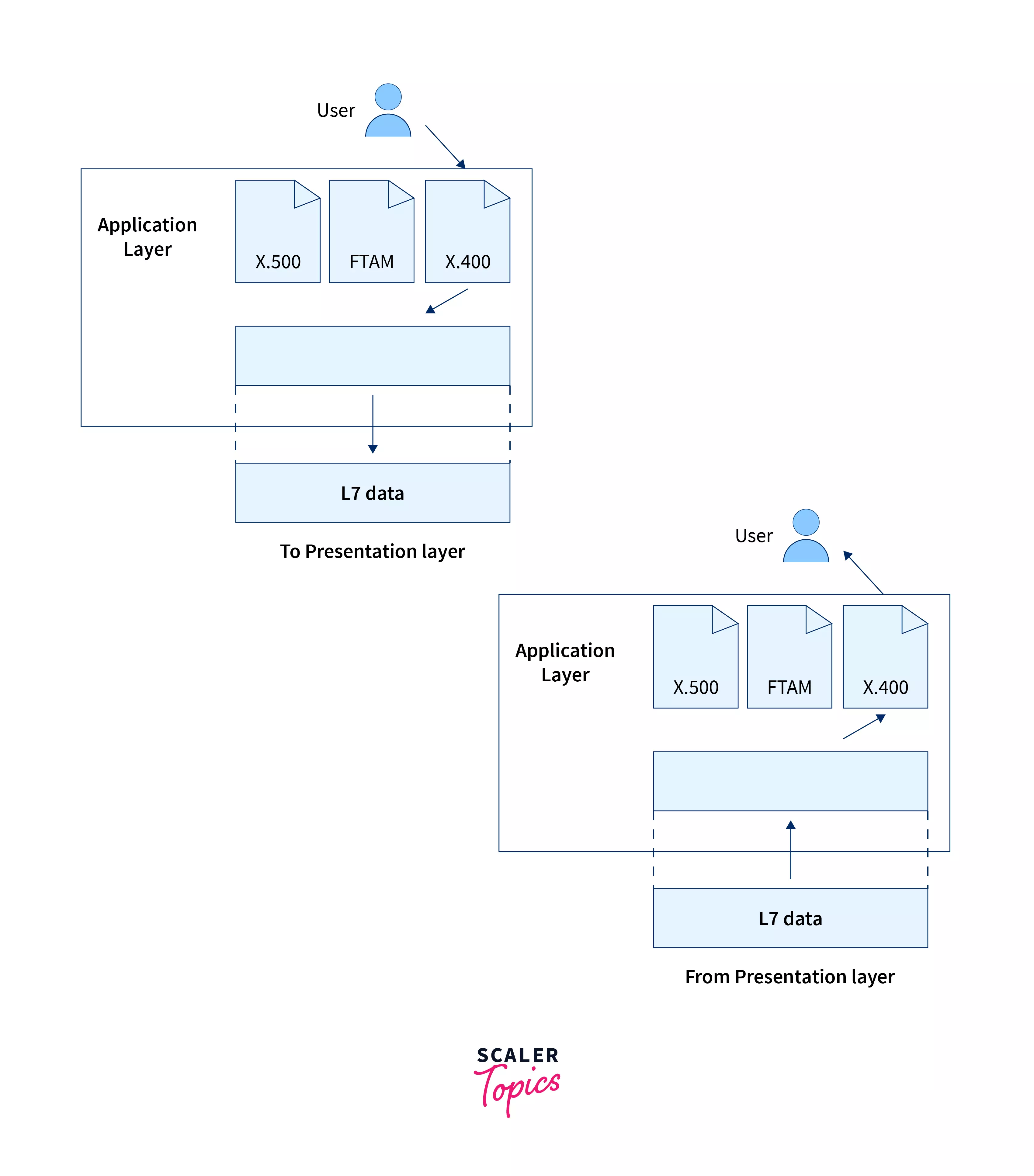
The application layer is the seventh and the last layer of the OSI model, which mainly concentrates on providing services to the users. The application layer contains numerous protocols that are used by users for different purposes (refer to the list provided at the end of this section for details).
Application layers allow users to access and share files, access and send emails, access webpages (via the world wide web), etc.
Refer to the image below to see the primary transmission of data and working of the application layer.
The various protocols used in this layer are:
- DNS (Domain Name System),
- SMTP (Simple Mail Transfer Protocol),
- FTP (File Transfer Protocol),
- POP (Post Office Protocol),
- HTTP (HyperText Transfer Protocol), etc.
The various devices used in this layer are:
- PC’s (Personal Computer),
- Phones,
- Servers,
- Firewalls, etc.
Advantages of OSI Model
Let us now discuss the various advantages of the OSI model:
- Using the OSI model, various other layered models are developed (for example – TCP/IP).
- Using the OSI model, we can see the big picture of the communication of data over the network.
- Each layer of the OSI model handles a specific job; hence can be handled and tested separately.
- The OSI model depicts how hardware and software work together.
- The OSI model can be used to compare the basic functional relationship on a different network.
- The OSI model provides abstraction so we can change any layer without thinking about other layers; hence, it can be easily used to incorporate new technologies.
Disadvantages of OSI Model
Let us now discuss the various disadvantages of the OSI model:
- There are some duplicate services provided by the various layers, for example – flow control, error control, etc.
- The OSI model is quite complex, slow, and costly to implement and use.
- The OSI model is theoretical, so it is not perfectly adequate for practical data transmission and communication.
Dive into the world of protocols and connectivity with our Computer Networking free course. Join today and learn from industry experts.
Conclusion
- The OSI model stands for Open Systems Interconnection model. The OSI model is also known as the ISO-OSI model because the OSI model was developed by ISO (International Organization for Standardization).
- The OSI model is a conceptual reference model that describes the entire flow of information from one computer to the other computer. The OSI model is a 7-layered model so it is also known as a 7-layered architecture model.
- The basic idea behind layered architecture is to divide the design into smaller pieces. Most networks are organized in a series of layers to reduce the design complexity.
- Each layer of the OSI model handles a specific job; hence can be handled and tested separately. The OSI model depicts how hardware and software work together.
- The OSI model provides abstraction so we can change any layer without thinking about other layers; hence, it can be easily used to incorporate new technologies.
- The OSI model is theoretical, so it is not perfectly adequate for practical data transmission and communication. It is quite complex, slow, and costly to implement and use.