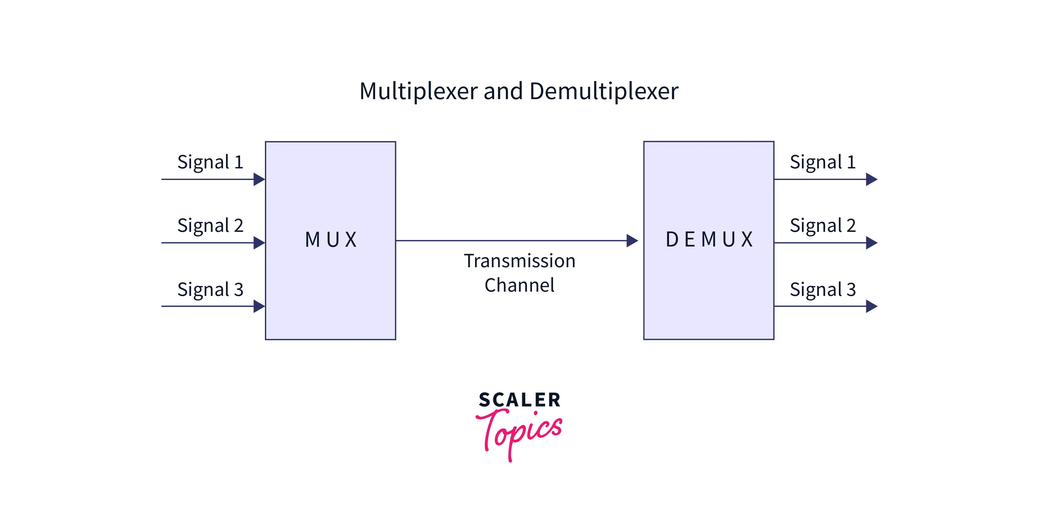
The process of multiplexing involves selecting an input line from the ‘n’ input lines and transmitting that selected line to the output line. The multiplexer is a device used for performing multiplexing. The demultiplexer is used for demultiplexing. And the demultiplexing process is just the reverse of the multiplexing process. Multiplexers and Demultiplexers are abbreviated as MUX and DEMUX.
What are Multiplexing and Demultiplexing in Computer Networks?
Mostly every protocol architecture uses Multiplexing and Demultiplexing in Computer Networks. Multiplexing and demultiplexing in transport layer protocol i.e. TCP and UDP are performed by adding the fields the source port number field and the destination port number field to its header.
- Multiplexing: Multiplexing is the process of collecting data from different application processes running on the sender’s end and then enveloping that gathered data with the header and then transmitting the whole to the receiver. The main purpose of multiplexing is to choose one of the n input lines and transmit it to the output.
- Demultiplexing: Working of demultiplexing is just the reverse of the multiplexing process and demultiplexing delivers the segment received from the receiver to the correct process of the application layer.
Refer to the below for the multiplexer and demultiplexer
What is a Multiplexer?
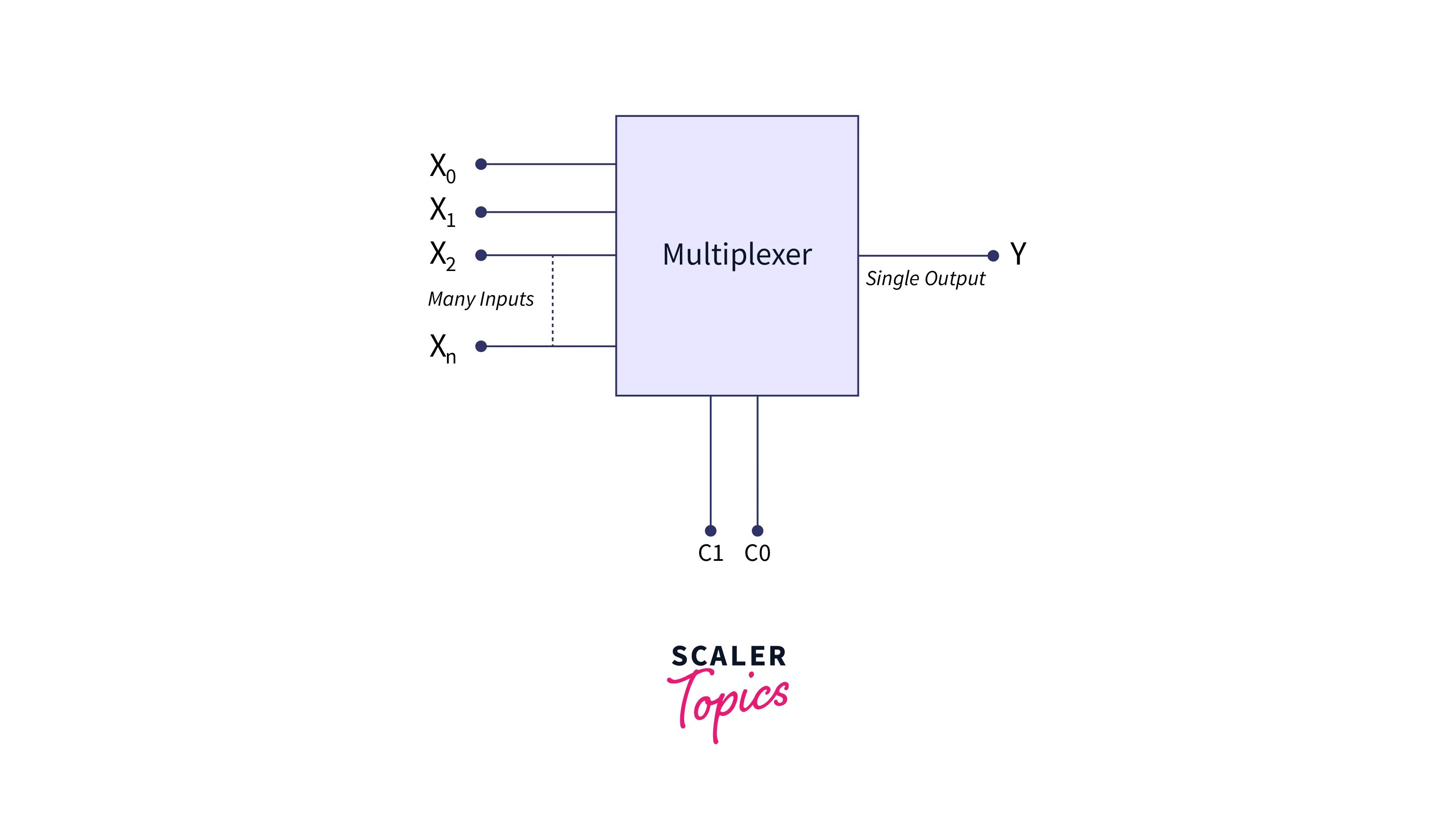
A multiplexer chooses a single input from the several inputs that can be transferred on a single line. MUX or Data selector is another name for the multiplexer.
The multiplexer is a device with multiple input lines and a single output line. Which input line is needed to be connected to the output line is decided by the select lines and data transmitted over the network within a certain time is also increased by it. That’s why it is also known as the data selector.
Refer to the below for the multiplexer
Both digital and analog applications can be handled by multiplexers. Relays and transistor switches are used for building multiplexers in analog applications while logic gates are used for building multiplexers in digital applications. The multiplexer is also known as a digital multiplexer when it is used in digital applications.
Types of Multiplexer
There are four types of multiplexers:
- 2-1 multiplexer(1 select line)
- 4-1 multiplexer(2 select lines)
- 8-1 multiplexer(3 select lines)
- 16-1 multiplexer(4 select lines)
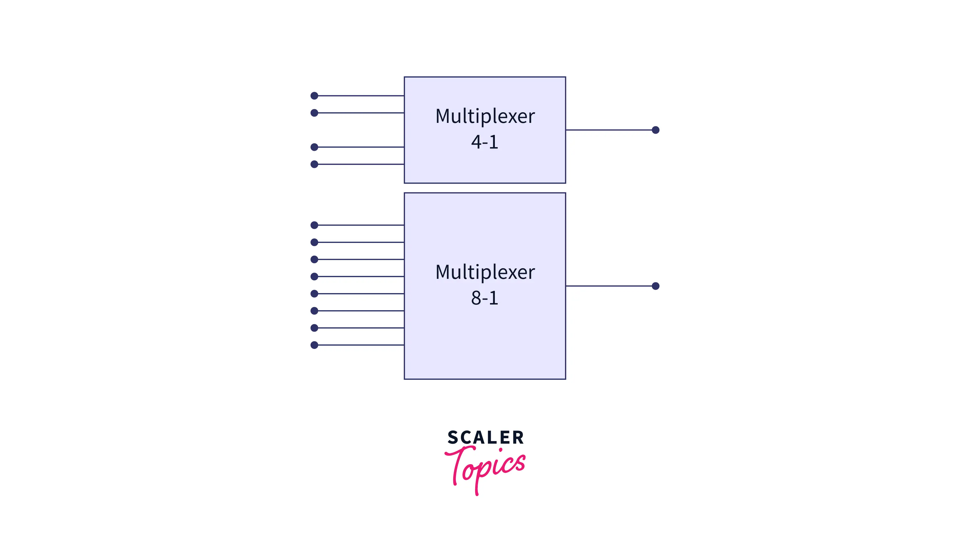
4-to-1 Multiplexer:
There are 4 input bits, 1-output bit, and 2-control bits in a 4X1 multiplexer. D0, D1, D2, and D3 represent four input lines and only one line is displayed in the output. The value of output q is dependent on the values of the control line AB. The below diagram represents the 4X1 multiplexer made using AND gates.
Refer to the below for the 4X1 multiplexer circuit
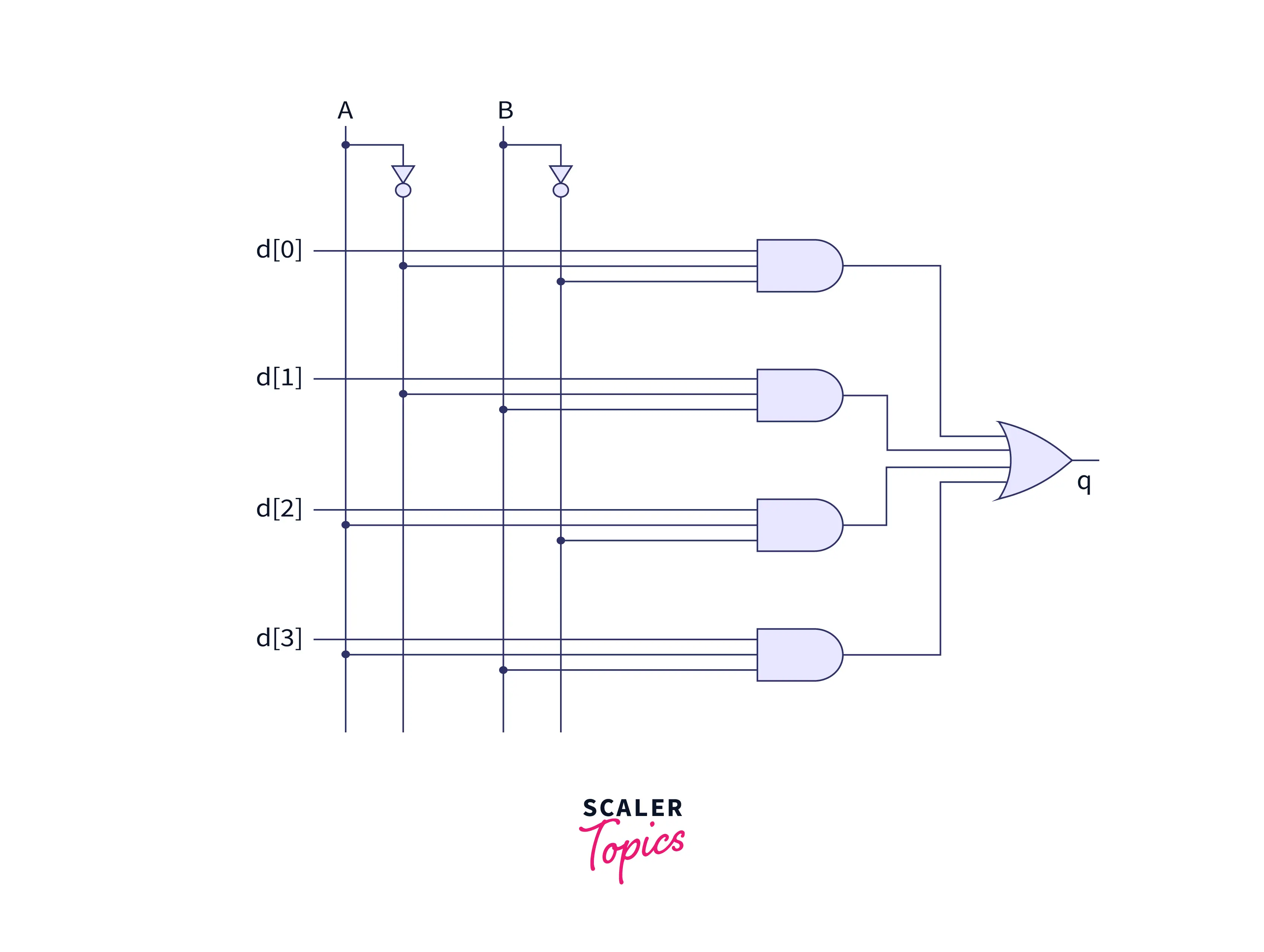
When the control bits are 00(AB=00) then the lower AND gates are restricted; only the AND gates that are higher are allowed. So input line D0 is transferred as output q.
When the control bits are 11(AB=11) then only the bottom AND gate is allowed and all other AND gates are restricted. So input line D3 is transferred as output q.
IC 74153, and IC 45352 are examples of multiplexers. In IC 74153, we get an output that is the same as an input and in IC 45352 we get a complement of input as an output.
8-to-1 Multiplexer:
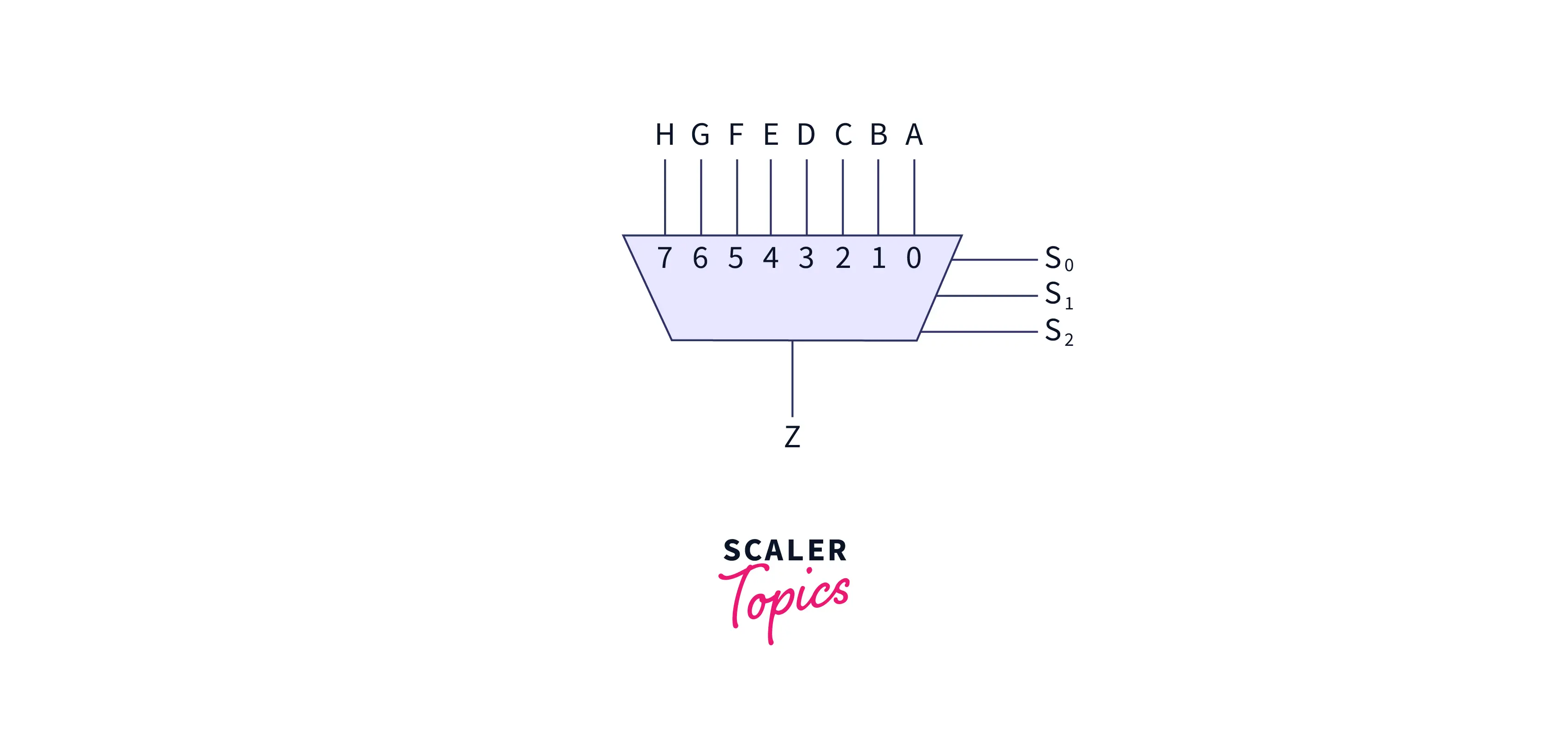
There are 8 input lines, 1 output line, and 3 selection lines in the 8-1 multiplexer.
Refer to the below for the 8-to-1 multiplexer
8 AND gates, 1 OR gate, and 3 NOT gates are required for building the 8X1 multiplexer. A combination of control lines and input data lines is given as input to AND gate.
Refer to the below for the 8X1 multiplexer circuit
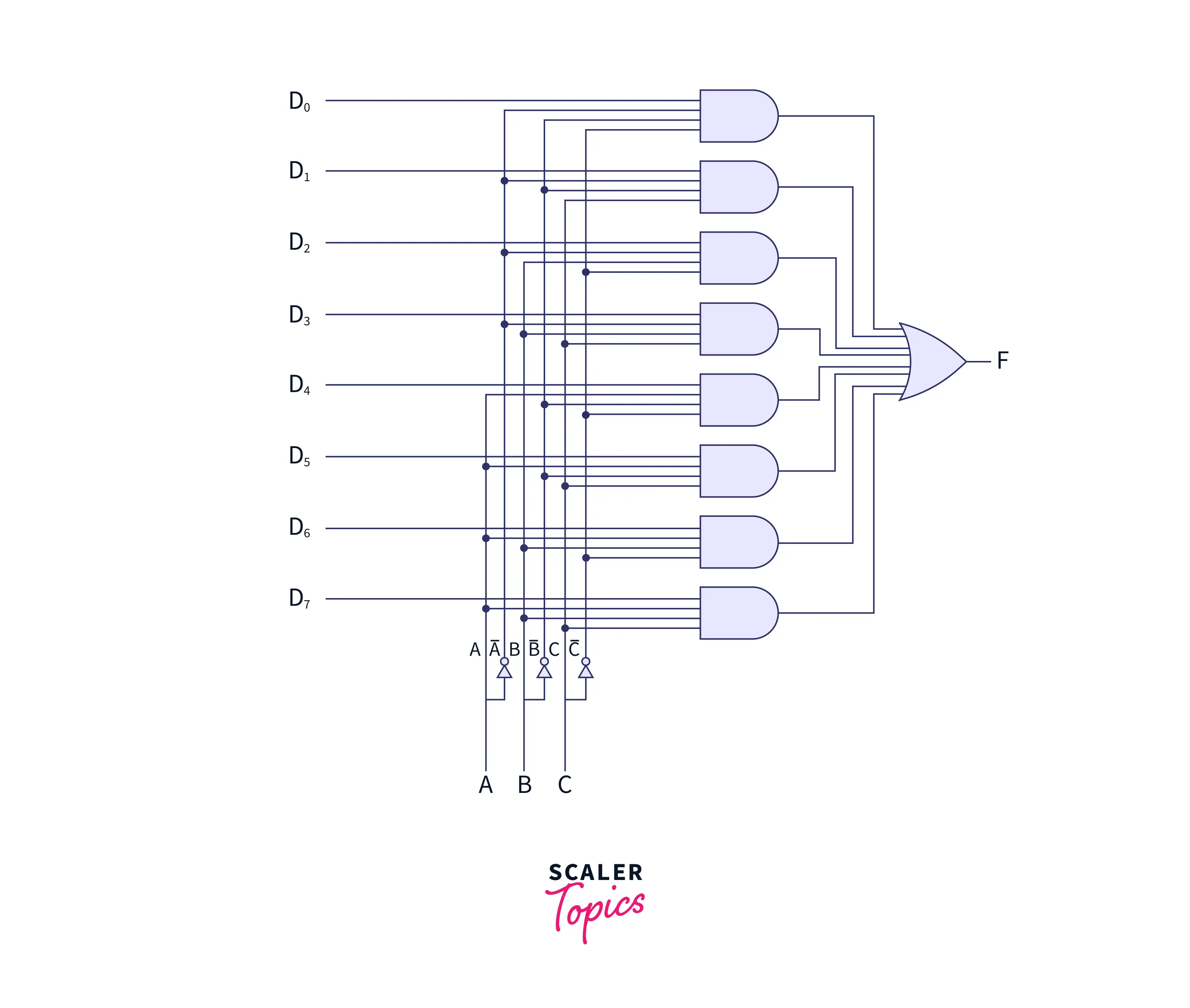
For every combination of control bits, only one AND gate gives 1 as an output and all other AND gates give 0 as an output. Then OR gate is used for adding the outputs of all the AND gates and this will give the selected value on output.
Advantages and Disadvantages of Multiplexer
Advantages of the multiplexer are given below:
- Multiplexer requires less number of wires
- Circuit complexity and cost are reduced by the multiplexer.
- There is no requirement for K-maps and simplification in the multiplexer.
- As the analog switching current ranges from 10mA to 20mA there is less heat dissipation in the multiplexer.
- Multiplexer is used for implementing several combinational circuits.
- Multiplexer also simplifies logic design.
Disadvantages of the multiplexer are given below:
- Additional I/O ports are used for controlling the multiplexer.
- There is a need to add the complexity of firmware for handling the switching ports.
Applications of Multiplexers
When there is a transmission of various data through a single line, then we use a multiplexer. Following are some of the applications of multiplexer:
- Communication System:
The communication system is the combination of both a communication network and a transmission system. The use of a multiplexer increases the efficiency of the communication system. As multiplexers provide the facility of transferring data such as video, and audio from various channels using only a single cable or line. - Computer Memory:
Multiplexers are used for the proper maintenance of the large size of memory in the computer system. It needs a few copper lines for the connection of memory to other parts of the computers. - Telephone Network:
Through the use of the multiplexer, various audio signals are combined into a single transmission line in a telephone network. - Transmission from the Computer System of a Satellite:
The multiplexer is used for the transmission of the data signal from the computer system available at a spacecraft or satellite to the ground system with the help of GSM.
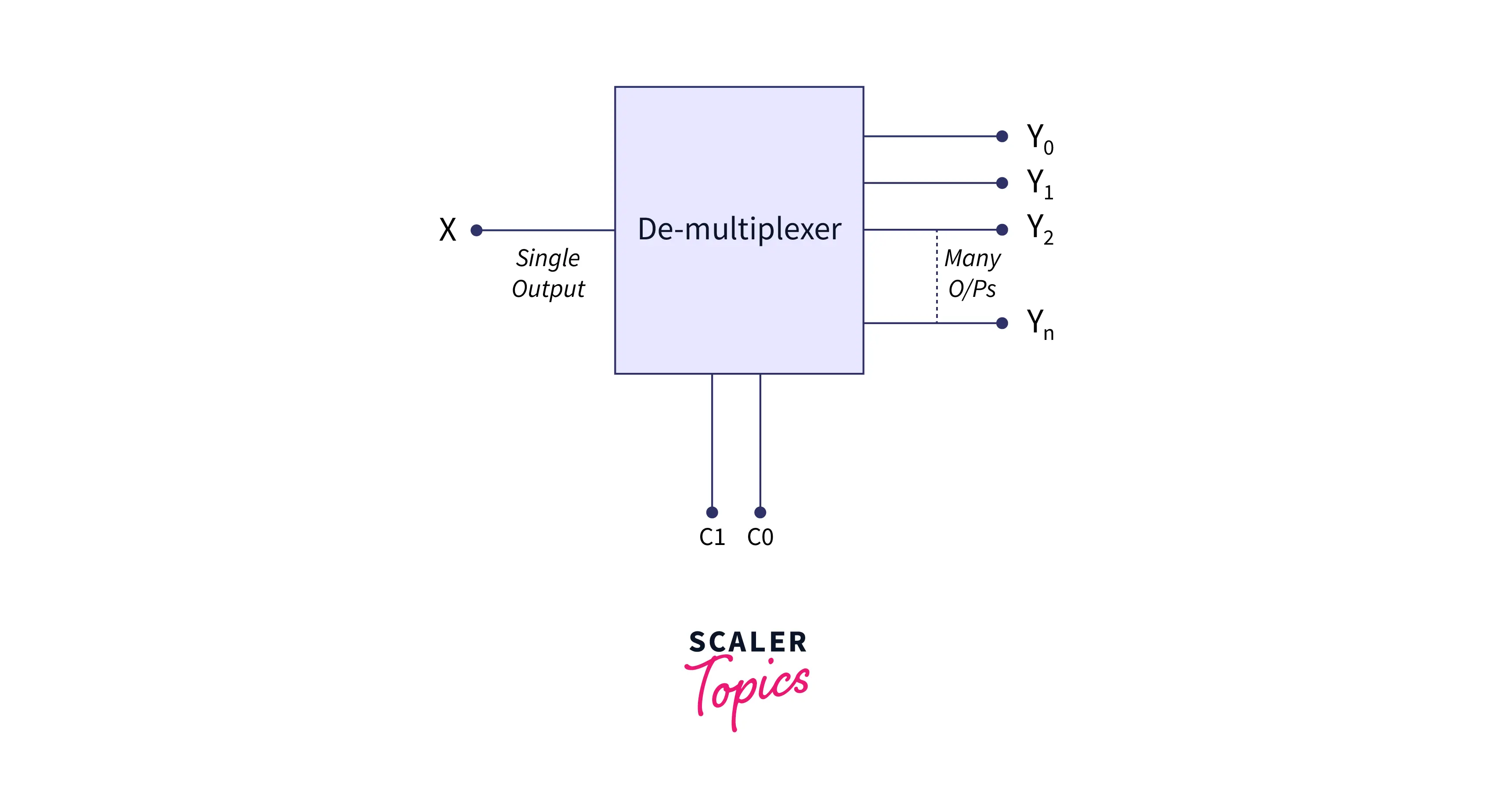
What is Demultiplexer?
A Demultiplexer is a device consisting of 1 input line and multiple output lines. The main difference between a multiplexer and a demultiplexer is that a multiplexer gives a single output Line by encoding multiple input lines and the demultiplexer performs the reverse function of the multiplexer.
Refer to the below for the demultiplexer
Types of Demultiplexer
There are four types of demultiplexer:
- 1-2 demultiplexer (1 select line)
- 1-4 demultiplexer (2 select lines)
- 1-8 demultiplexer (3 select lines)
- 1-16 demultiplexer (4 select lines)
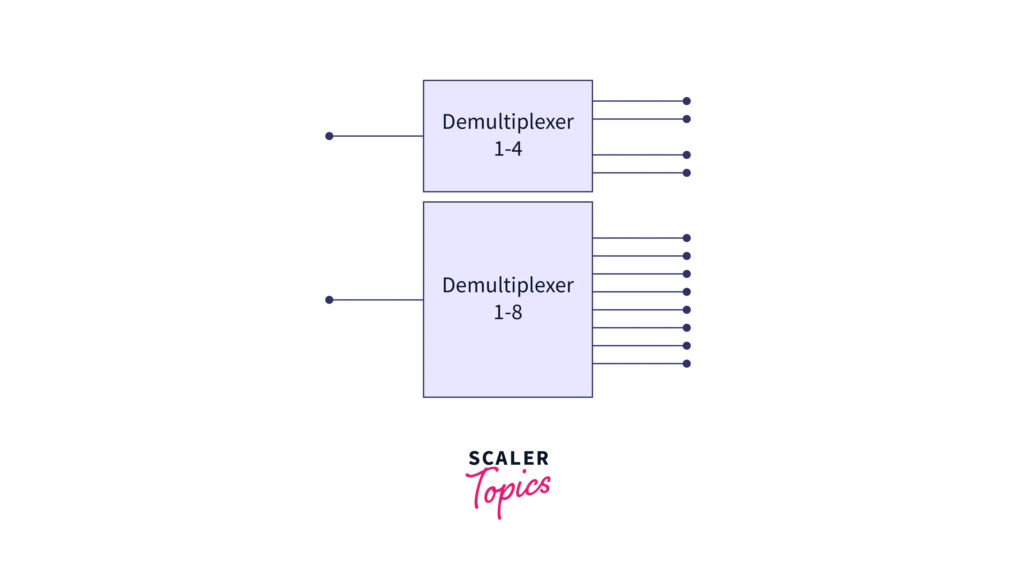
1-4 Demultiplexer:
There is 1 input line, four output lines and control bits in 1-4 demultiplexers. The circuit diagram of 1-4 demultiplexer is given below:
Refer to the below for the 1X4 demultiplexer
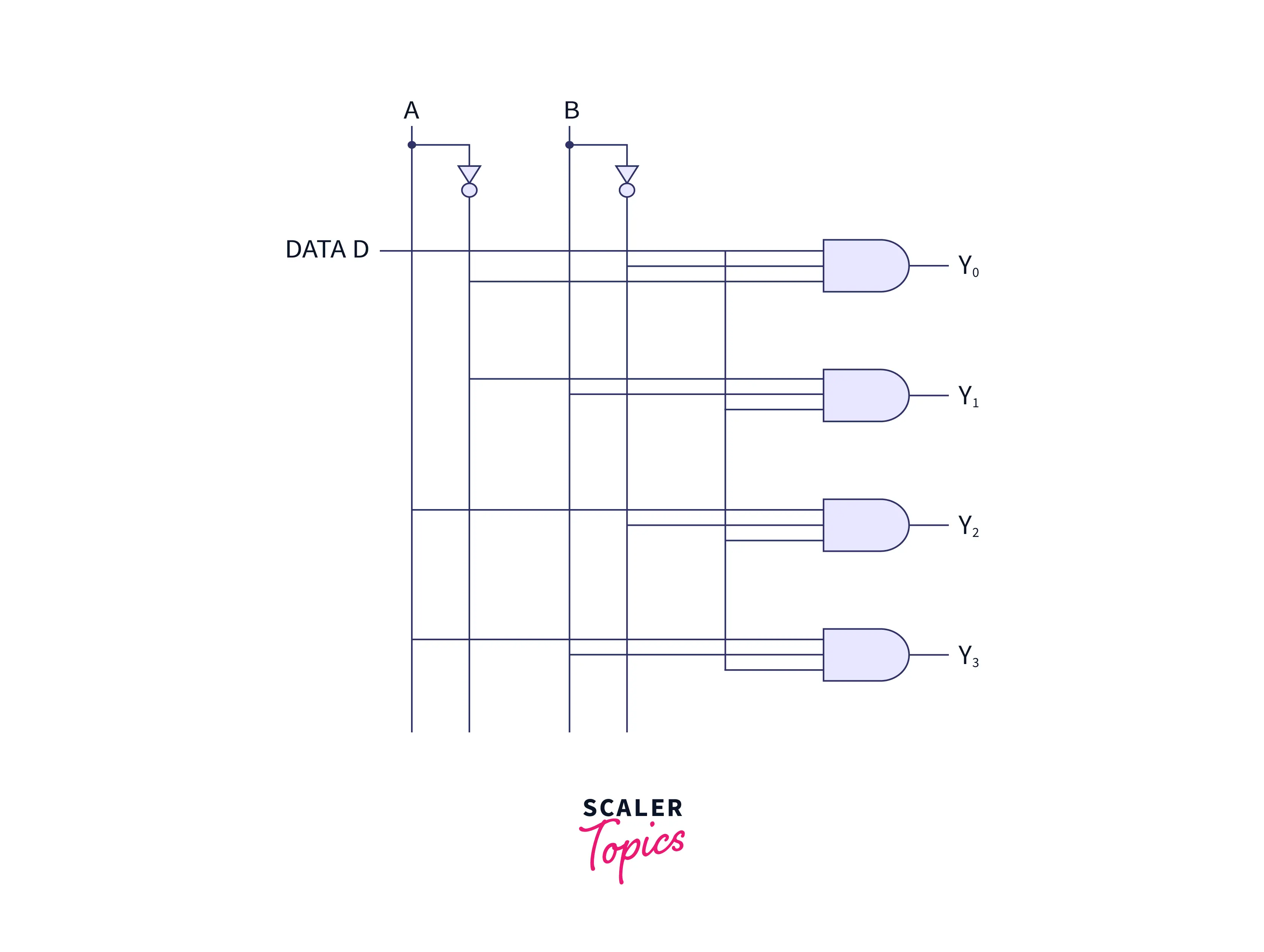
The input bit is represented by Data D. This input data is sent on the output lines which is dependent on the value of control bits AB.
When the control bit AB is set as 01 then the second AND gate is permitted and all other AND gates are restricted So input data but D is transmitted to output Line Y1 and y1=D.
If data bit D is given low as input then the output at Y1 is also low and if it is given high then the output at Y1 is also high. So output Y1 value also depends on the input data bit D.
IC 74155 is the best example of a 1-4 demultiplexer.
1-8 Demultiplexer:
Data distributor is another name for the 1-8 demultiplexer because it consists of 1 input, 3 control lines, and 1 output line. 1-8 multiplexer uses AND gate for switching the input line into one of the output lines.
Refer to the below for the 1-8 demultiplexer circuit
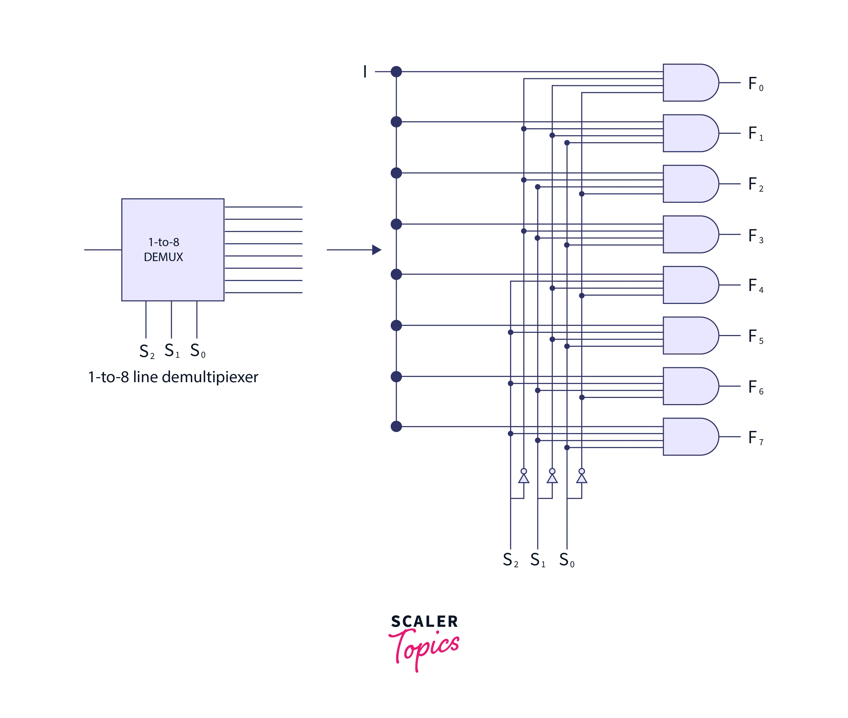
D represents the input bit and this input data is sent to the output lines. And the output is dependent on the value of the control bits AB. When the value AB is 01, all AND gates are disabled, except the upper second gate F1 which is the only enabled gate, and the input data bit is sent to the output and F1=data. And if the input value of D is low, then the value of F1 and if the D value is high then the value of F1 is high.
Advantages and Disadvantages of Demultiplexer
Following are some advantages of using demultiplexer:
- For the partition of the mutual signals back into the separate stream, we used the demultiplexer or demux.
- There is a requirement for a combination of mux and demux for the transmission of audio or video signals.
- In the Banking department, demux can also be used as a decoder for security purposes.
- The Combination of mux and demux can lead to an increment in the efficiency of the communication system.
Following are some disadvantages of using demultiplexer:
- There is a possibility of delay due to the synchronization of signals.
Applications of Demultiplexer
For the connection of a single source to various destinations, we used demultiplexers. Some of the applications of the multiplexers are given below:
- Communication System:
For the implementation of data transmission, both mux and demux are used in the communication system. The output signals are received by the demultiplexer from the multiplexer and after that de-multiplexer converts these signals back to their original form. - Arithmetic Logic Unit:
Demultiplexer takes the output of the ALU as an input. And various registers are connected with the output of the demultiplexer. ALU’s output is stored in different registers. - Serial to Parallel Converter:
Serial to parallel converter is designed for recreating the parallel data. In this converter, demultiplexers get input in the form of serial data at regular intervals of time. For deducting the data signals at the output of the demultiplexer, there is a counter that is attached to the control unit of the demultiplexer. In Parallel form, the output of the demultiplexer can be read, when all the data signals are stored.
How Multiplexing and Demultiplexing Done?
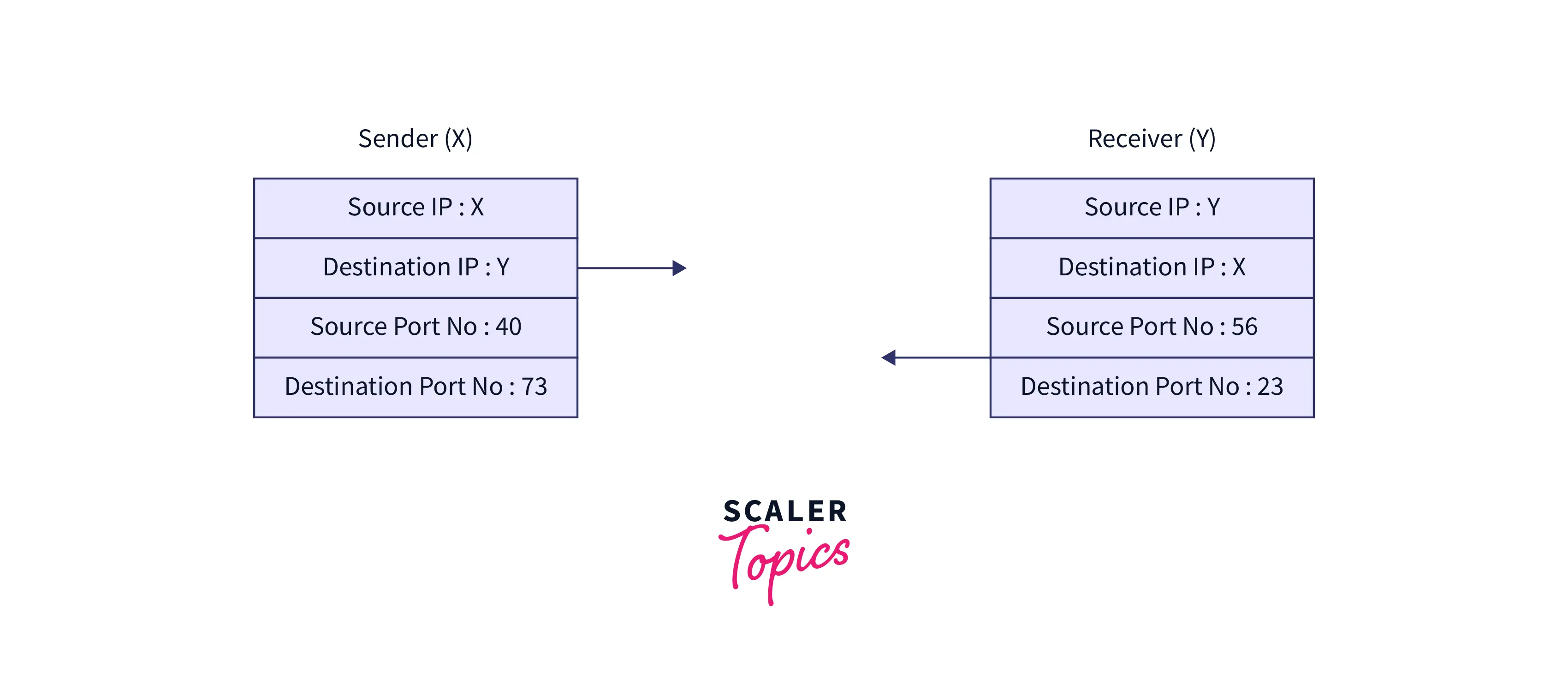
If data is transferred from an application present on the sender node to the application present on the destination node then, it is mandatory for the sender to know the IP address of the destination node and also the port number of the application present at the destination node.
Refer to the below for the multiplexing and demultiplexing process
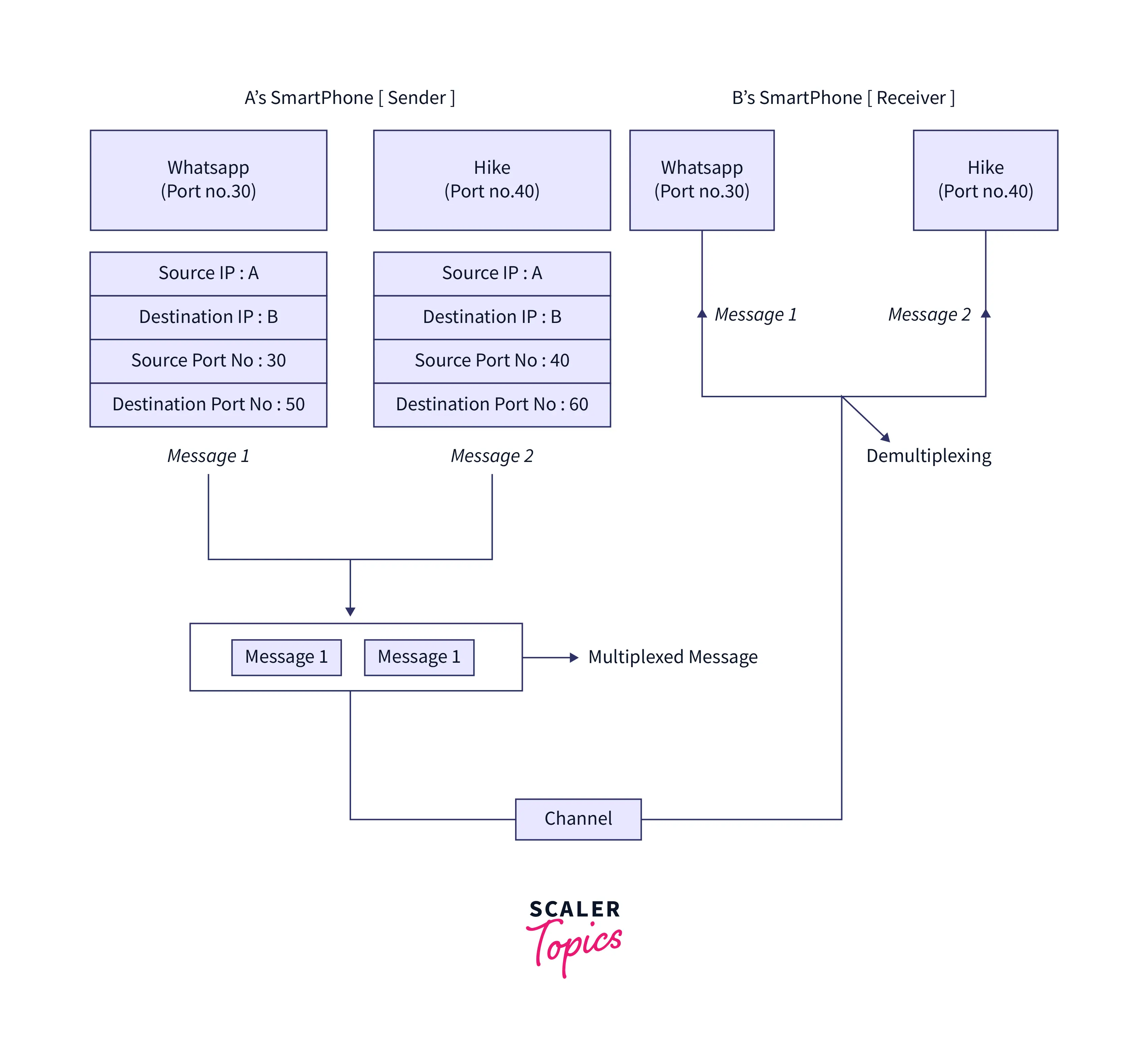
Transmission of packets takes place between the applications of the sender and receiver side. For a better understanding of the process of multiplexing and demultiplexing in the computer network, let’s take the example of two messaging apps that are commonly used in this modern world that are hike and WhatsApp. Let A be the sender and B be the receiver. It is mandatory for both the sender and receiver to install these applications on their systems. If A wants to send some message to B through WhatsApp and Hike. So, for sending a message to B, A must mention the IP address of B and also the destination port number of WhatsApp or any other messaging application through which it transfers messages. Repeat the same process for transmitting messages using the hike application.
Now the messages from both applications will be combined with all the necessary headers such as the IP address of the sender, IP address of the receiver, port number of the sender, port number of the receiver, etc. This wrapped message with all headers transferred to the destination node as a single message only. The above-defined process is known as demultiplexing. B is also allowed to transfer any message to A. On the receiver side, after receiving the message, data is unwrapped, and messages from both applications transfer according to their destination port number.
Refer to the below for the process of multiplexing and demultiplexing in computer networks
Difference between Multiplexing and Demultiplexing in Computer Networks
Below are the differences that differentiate Multiplexing and Demultiplexing in Computer Networks
| Multiplexing | Demultiplexing |
|---|---|
| Multiplexing is a process in which various data signals are integrated to give a single output. | Demultiplexing is a process in which one input data signal is divided into various output signals. |
| It takes various input signals and gives one output signal only. | It provides multiple output signals and takes one input signal only. |
| Serial to parallel conversion is used in multiplexing. | Parallel to serial conversion is used in demultiplexers. |
| Example: For 8 inputs there is 1 output, for 16 inputs there is 1 output, for 32 inputs there is 1 output. | Example: For 1 input there are 8 outputs, for 1 input there are 16 outputs, for 1 input there are 32 outputs. |
| Refer to the below image for the multiplexing | Refer to the below image for the demultiplexing |
 |  |
Key Difference between Multiplexer and Demultiplexer
| Multiplexer | Demultiplexer |
|---|---|
| The multiplexer is abbreviated as MUX. | The demultiplexer is abbreviated as DEMUX. |
| A multiplexer can be defined as a digital switch. | A Demultiplexer can be defined as a digital circuit. |
| The multiplexer works as a data selector. | The demultiplexer works as a data distributor. |
| Working of multiplexers is based on many to one principle. | Working of demultiplexers is based on one too many principles. |
TDM(Time Division Multiplexing) uses a multiplexer at the sender’s end. | TDM(Time Division Multiplexing) uses a demultiplexer at the receiver’s end. |
Time-division multiplexing is abbreviated as TDM and it is a multiplexing technique in which multiple data streams are put in a single signal by making the segments of the signal by separating, and every segment has a short time duration.
Enroll in our Free Computer Networks course specially curated by industry experts. Sign up today get certified for free!
Conclusion
- A multiplexer chooses a single input from the several inputs that can be transferred on a single line.
- 2-1 multiplexer, 4-1 multiplexer, 8-1 multiplexer, and 16-1 multiplexer are the types of the multiplexer.
- A Demultiplexer is a device consisting of 1 input line and multiple output lines.
- 1-2 demultiplexers, 1-4 demultiplexers, 1-8 demultiplexers, and 1-16 demultiplexers are the types of demultiplexers.
- The main difference between the multiplexer and a demultiplexer is that a multiplexer transmits a single output line by encoding multiple input lines and a demultiplexer just reverses the multiplexing process.
- Multiplexing and demultiplexing in transport layer protocol i.e. TCP and UDP are performed by adding the fields the source port number field and the destination port number field to its header.