All protocol architectures that have ever been created offer multiplexing and demultiplexing features. The source port number field and the destination port number field are two unique fields that UDP and TCP use to conduct the demultiplexing and multiplexing tasks in the segment headers.
Multiplexing is the act of assembling data from several application processes of the sender, including that data in a header, and transmitting the entire collection to the designated recipient.
Demultiplexing is the process of transferring segments that have been received to the appropriate app layer operations at the recipient side.
UDP/TCP Connection
TCP
Transmission Control Protocol is known as TCP. If we desire effective and dependable communication between two computers, such communication must be good. For instance, if we want to see a web page, we anticipate that nothing should be missing from the page, and if we want to download a file, we need a whole file, meaning that neither a text nor an image should be absent. The TCP is the only thing that makes this feasible. One of the most used protocols on the TCP/IP network is.
Features of TCP
The TCP has the Features Listed Below:
- Delivery of Data:
The TCP protocol makes sure that the data is accurately received, complete, and in the right sequence. If the TCP protocol is not used, erroneous or out-of-order data may be received. For instance, certain data or graphics may be missing if we attempt to read a web page or download a file without utilizing TCP. - Protocol:
TCP is a connection-oriented protocol. The phrase “connection-oriented” implies that the computers first create a link before engaging in conversation. A three-way handshake is used to accomplish this. In a three-way handshake, the first sender transmits the SYN message to the receiver, who then replies with theSYN-ACKmessage to acknowledge receipt of the message. The acknowledgment message is sent by the sender to the recipient upon receipt of theSYN-ACKmessage. The link between the computers is formed in this manner. The data will be transmitted after the connection has been made. Because of this protocol’s data delivery guarantee, TCP will resend the data if it is not received the first time.
UDP
User Datagram Protocol(UDP) is the name of the protocol. Given that it is utilized for both messages sending and receiving, its operation is comparable to that of TCP. The primary distinction is the connectionless nature of UDP. In this context, the term “connectionless” denotes the absence of a connection before communication. Additionally, it is not certain that data packets will be delivered. It is sometimes referred to as the “fire-and-forget” protocol since it is unconcerned with whether the data has been received on the receiver’s end or not. The “fire-and-forget” protocol is another name for it since it delivers data regardless of whether it is received or not. Because UDP does not guarantee packet delivery, it is quicker than TCP.
To ensure order, dependability, and data integrity, UDP employs a straightforward transmission technique. To minimize the cost associated with such processing at the network interface level, UDP also presupposes that error checking and repair are not significant or are not carried out in the application. Multicasting and packet transmissions are also compatible with it.
Multiplexing
A device known as a multiplexer splits the physical channel and allows one to each sender when many senders attempt to broadcast over a single media. A De-multiplexer on the receiving end of the transmission gets data from a single media, distinguishes each one, and delivers it to several receivers.
Multiplexing, often known as muxing, is a technique used in telecommunications and computer networking to combine several analog or digital signals into a single signal via a common media. The goal is to share a physical transmission medium, a limited resource. For instance, many phone calls might be sent through one line in telecommunications. In the 1870s, telegraphy gave rise to multiplexing, which is currently a common practice in communications. The invention of telephone carrier multiplexing in telephony is attributed to George Owen Squier in 1910.
A device that multiplexes data is referred to as a multiplexer (MUX), while a device that demultiplexes data is referred to as a demultiplexer (DEMUX or DMX). The goal of inverse multiplexing (IMUX), which is the reverse of multiplexing, is to divide one data stream into several streams, send them all through various communication channels at once, and then reconstruct the original data stream.
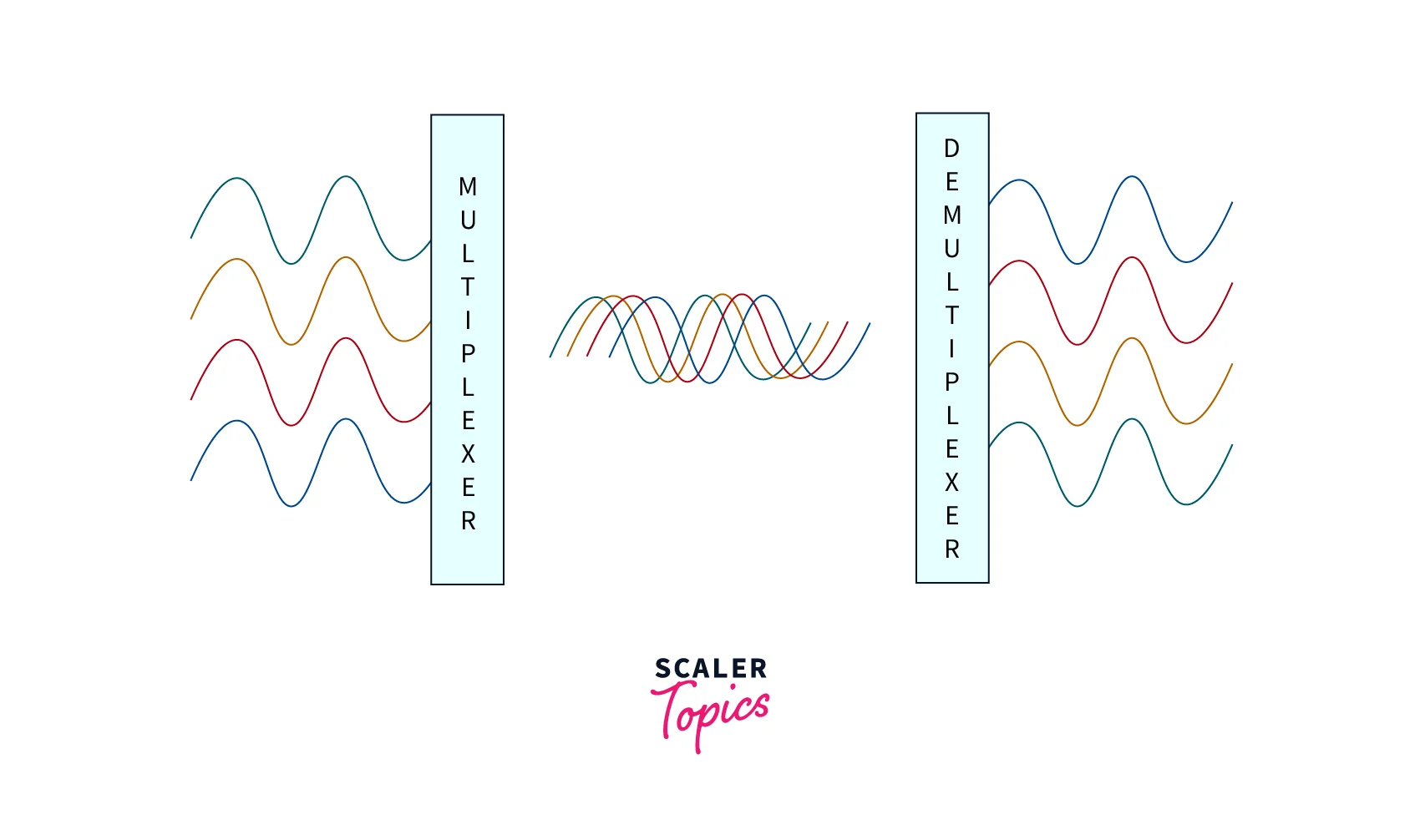
Frequency Division Multiplexing
FDM is utilized when the carrier is frequency. An analog technique is FDM. FDM assigns one user to each channel after dividing the spectrum or carrier bandwidth into logical channels. The channel frequency is available to each user solely and can be used separately. Each channel has a separate section so that none of them overlap. Guard bands are used to divide the channels. A guard band is a frequency that neither channel uses.
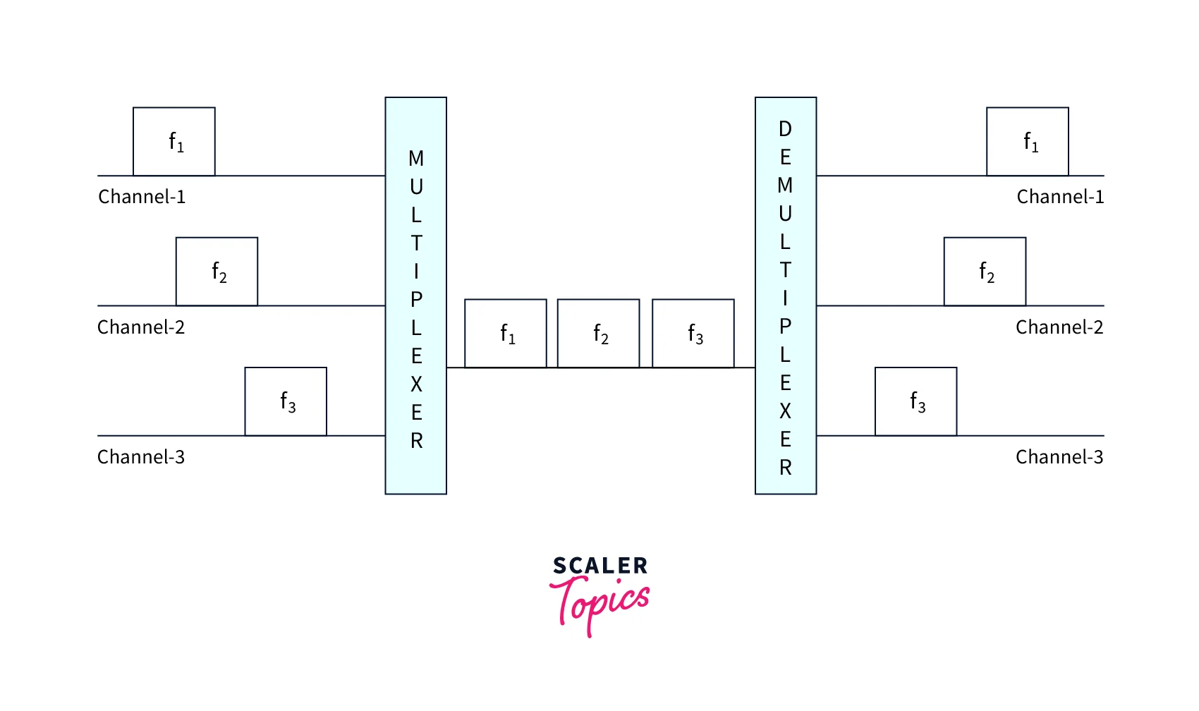
Multiplexing With Time Division
TDM is usually used with digital communications, while it may also be used with analog signals. Time slots are used in TDM to split the shared channel among its users. Each user is limited to sending data during the allotted period. Digital signals are split into frames, which correspond to time slots, i.e., a frame of the best size that can be transmitted during a specific time slot.
In synchronized mode, TDM operates. Multiplexer and De-multiplexer are both timely coordinated and concurrently transition to the next channel.
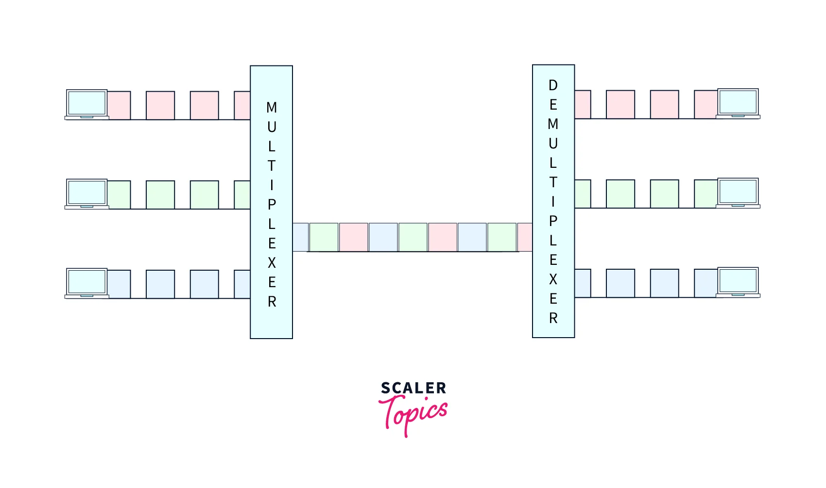
The De-multiplexer feeds channel A with media when channel A broadcasts its frame at one end. This site changes to channel B as soon as the time window for channel A ends. Channel B receives media from the De-multiplexer, which operates in synchrony on the opposite end. The route is used to interleave the signals coming from many channels.
Wavelength Division Multiplexing
The De-multiplexer feeds channel A with media when channel A broadcasts its frame at one end. This site changes to channel B as soon as the time window for channel A ends. Channel B receives media from the De-multiplexer, which operates in synchrony on the opposite end. The route is used to interleave the signals coming from many channels.
Additionally, time division multiplexing can be added to each wavelength to allow additional data transmissions.
Code Division Multiplexing
Code Division Multiplexing is a technique for transmitting several data streams over a single frequency. While FDM divides the frequency into smaller channels, CDM allows users to utilize the entire bandwidth and broadcast signals continuously using a special code. To distribute signals, CDM employs orthogonal coding.
A special code, known as a chip, is given to each station. These codes enable independent signal transmission throughout the whole bandwidth. The chip code signal that has to be received is known in advance by the receiver.
Demultiplexing
Demultiplexing (Demuxing) is a word used for multiplexing. It is the multiplexing process done backward. Demultiplexing is the process of turning a transmission that contains multiple analog or digital signal streams back into the original, independent signals.
Demultiplexing is not the inverse of multiplexing, even though it is the multiplexing process’s opposite. Inverse multiplexing (muxing), which divides one data stream into numerous related data streams, is the reverse of multiplexing.
Demultiplexing and inverse multiplexing are hence different in that the output streams of the former are unconnected while the latter is.
Devices that perform the multiplexer’s opposite function are known as demultiplexers (Demux).
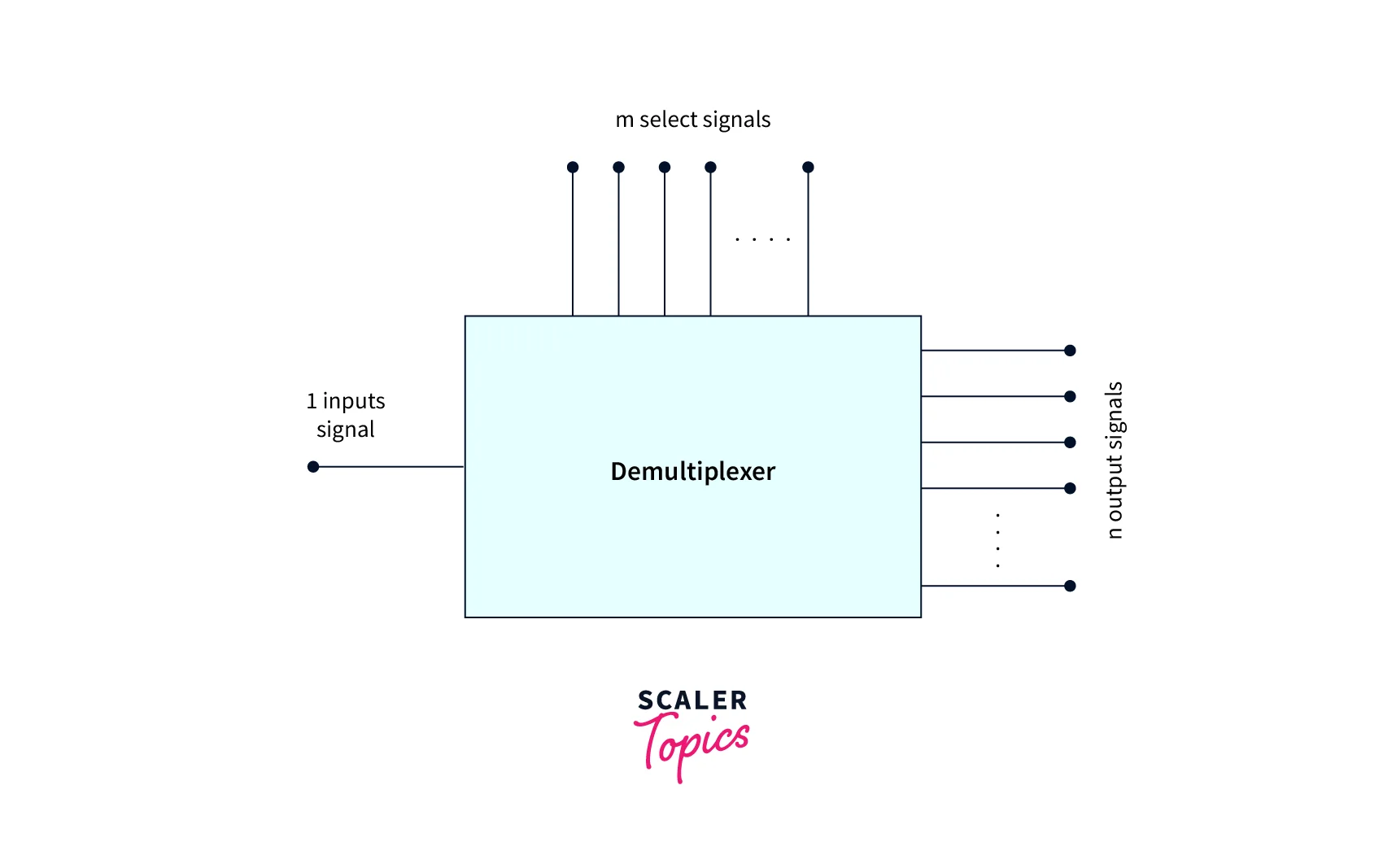
A data distributor known as a demultiplexer is pronounced DEMUX. The opposite of a multiplexer or MUX is this. It involves accepting data from one input and sending it via one or more outputs.
Demultiplexer (Demux):
- In a communication system, this device takes the output signals from the multiplexer and restores them to their original state at the receiving end.
- The output of the arithmetic logic unit feeds into the demux’s input, and the demux’s output is connected to several registers in the arithmetic logic unit.
- Data reformatting is done using the serial to the parallel converter in the serial to parallel converter. According to this technique, serial data are provided to the Demux as input, and the Demux is equipped with a counter that senses the data signal at the Demux’s output. The output of the Demux may be read out simultaneously once all data signals have been saved.
Types of Demultiplexer
Various varieties of demultiplexers, including 1 to 2, 1 to 4, 1 to 8, and 1 to 16, are available based on the varied output configurations. There are several different IC packages for these demultiplexers. Some of them include the 74139 IC, which is a dual 1 to 4 Demux, the 74138 IC, a 1 to 8 Demux, the 74237 IC, a 1 to 8 Demux with address lines, the 74154 IC, a 1 to 16 Demux, and the 74159 IC, an open collector 1 to 16 Demux. Decoder ICs is another name for the Demux ICs.
1 to 4 Demultiplexer
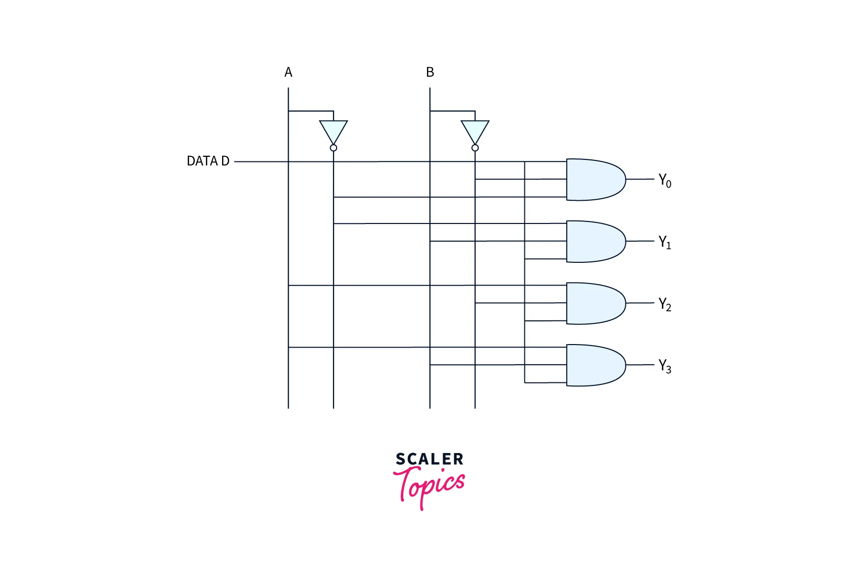
A control bit, four output bits, and one input bit make up the 1-to-4 demultiplexer. Below is a circuit schematic for a 1X4 demultiplexer.
Data D with two select lines A and B serves as the input bit. Four output bits, Y0, Y1, Y2, and Y4, receive the input bit D.
If AB is 01 When compared to the other AND gate, the top second AND gate is turned on. Thus, at Y1, just one data is sent. Y1 is low if D is low, while Y1 is high if D is high. D‘s value determines how much Y1 is worth.
Truth Table
The 1 to 4 demultiplexer’s truth table is shown below:

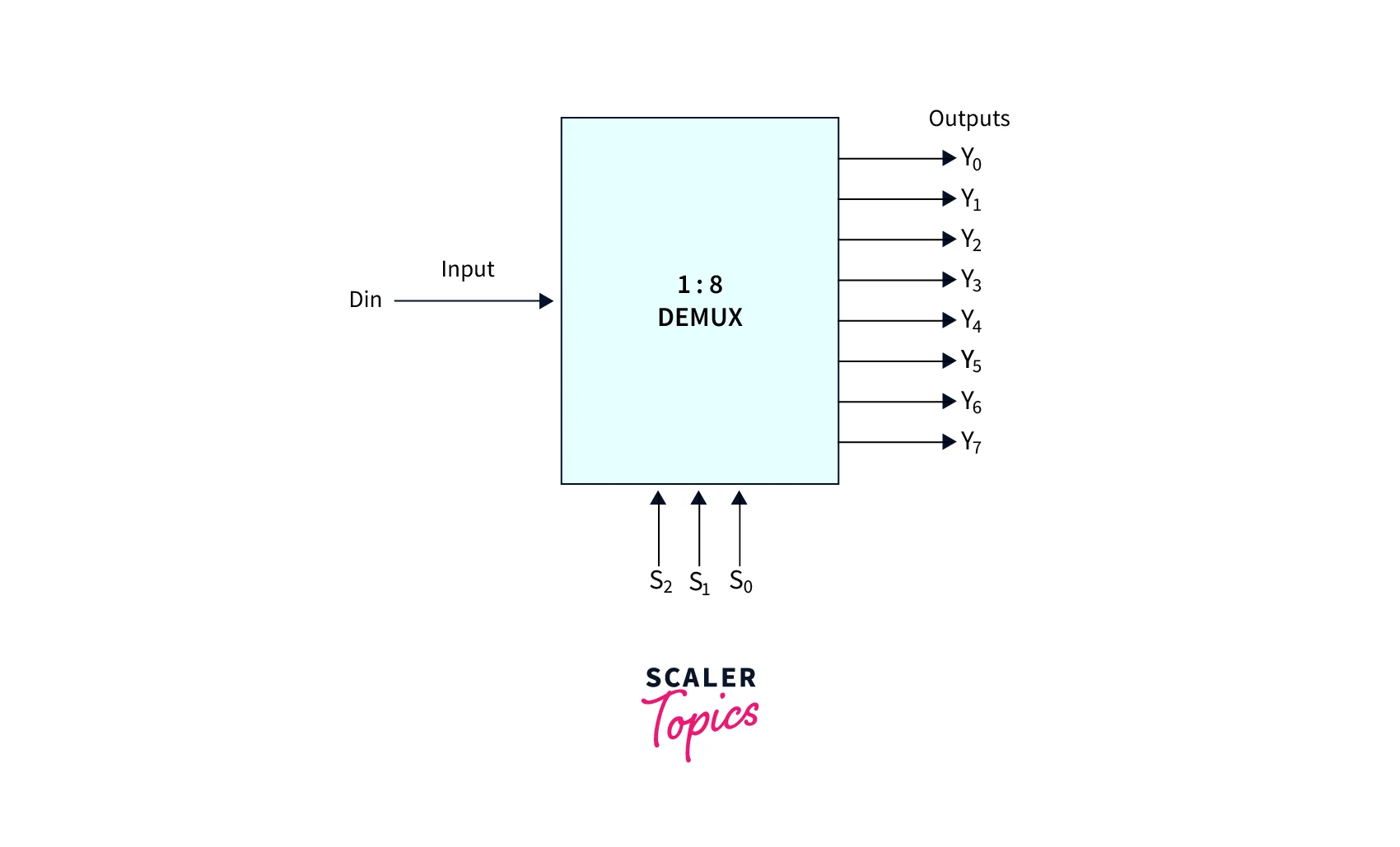
1–8 Demultiplexer
One input line, eight output lines, and three select lines make up a 1 to 8 demultiplexer (or multiplexer). Assuming inputD, two select lines (S1 and S2), and eight outputs (Y0 to Y7) are all present. Due to the 3 selection lines, it is also known as 3 to 8 demux. The block diagram for the 1 to 8 demux may be found below.
Truth Table
The truth table for the 1 to 8 demultiplexer is shown below. It describes the demux’s capabilities, such as how the output appears at Y0 if S1S2S0=000, and so on.
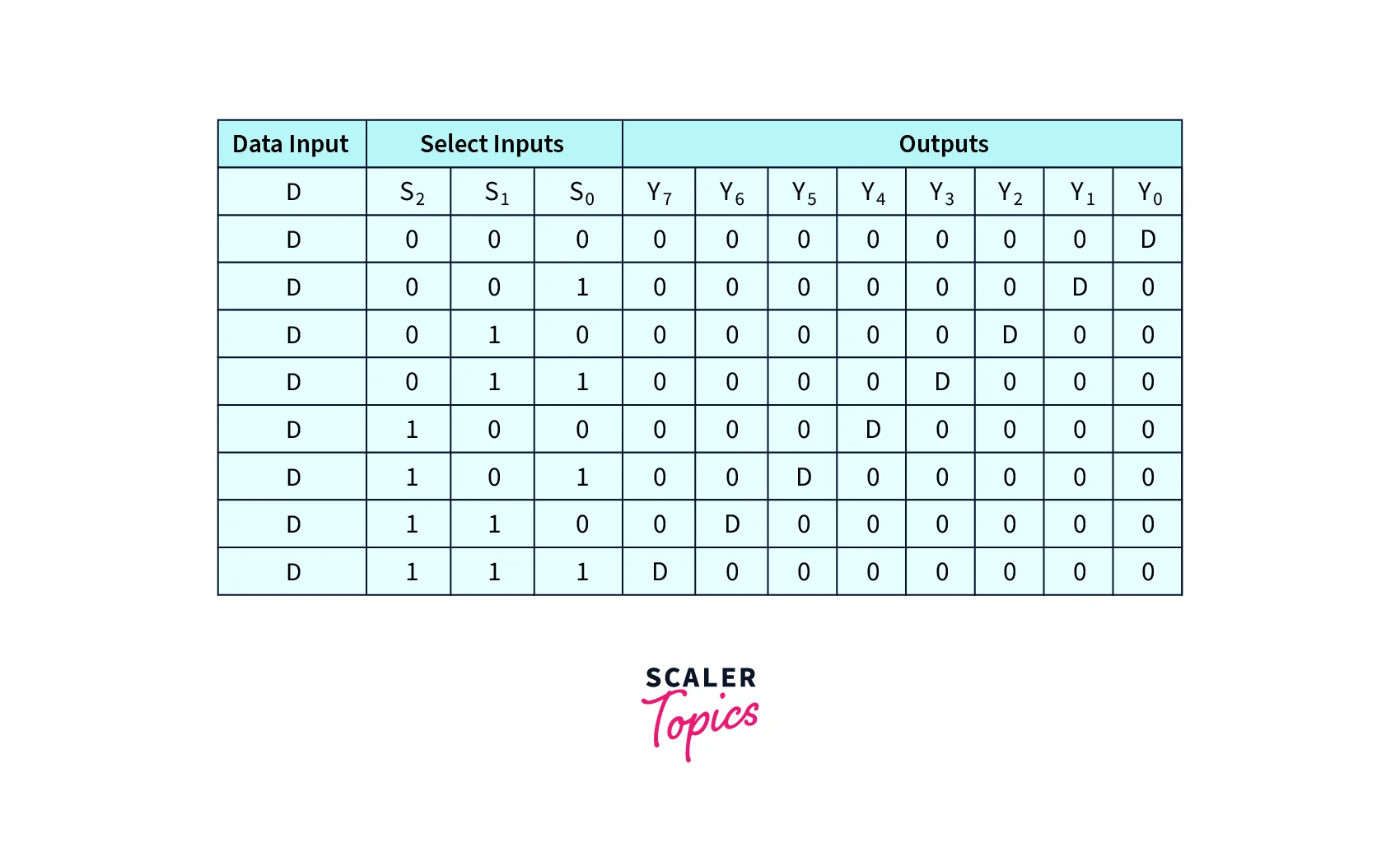
With the help of the aforementioned truth table, eight AND gates and three NOT gates are used to create the demultiplexer’s logic diagram. To ensure that data input is shown at a certain output, distinct select line combinations choose one AND gate at a time.
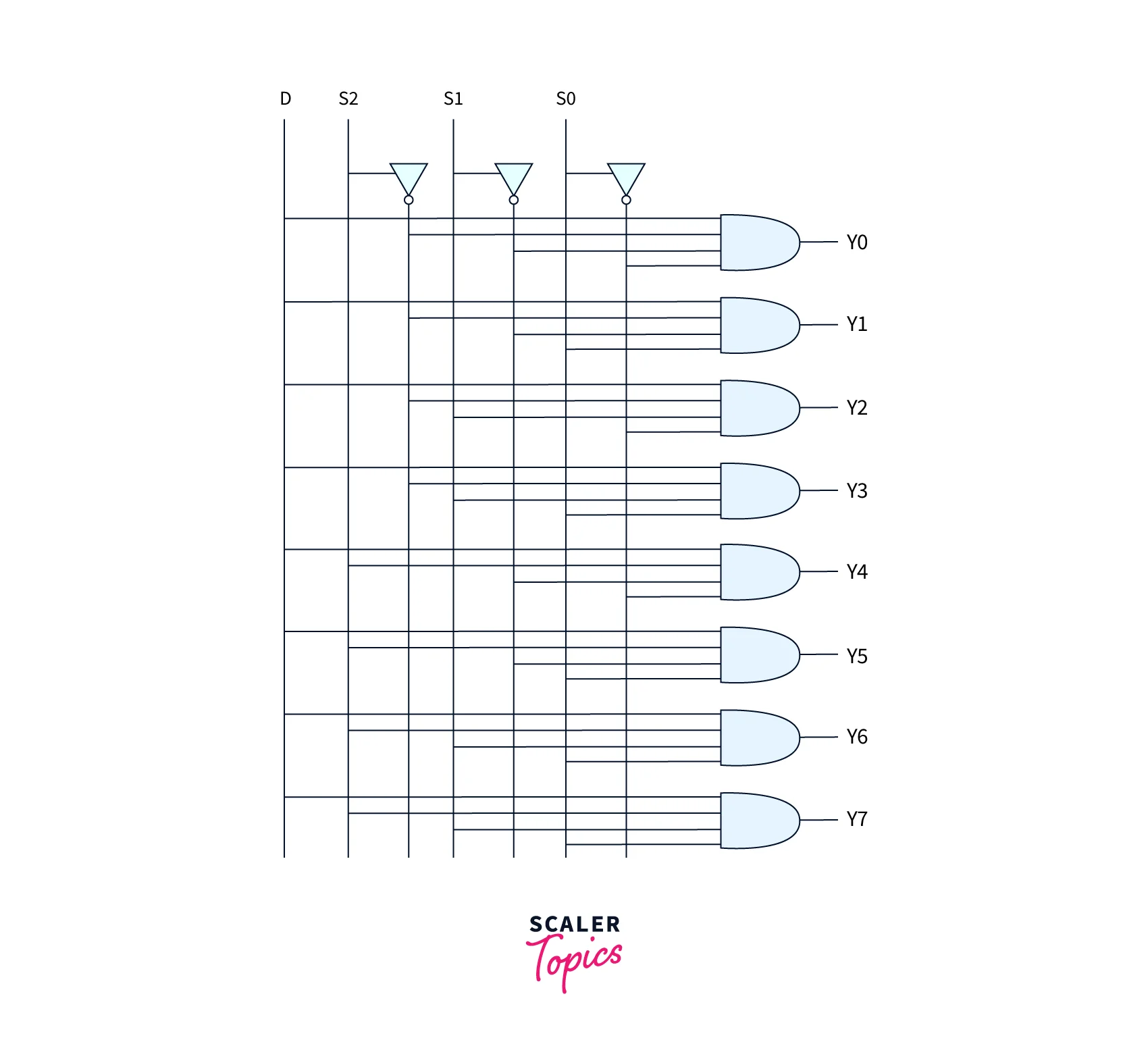
Two 1 to 4 demultiplexers can be used to build a 1 to 8 demultiplexer. Smaller demux is used to create large demultiplexers since it is more complicated to implement demultiplexers with large outputs.
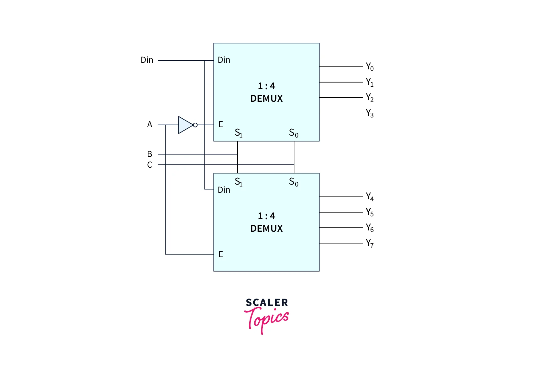
1 to 16 Demultiplexer
The 1 to 16 demultiplexer contains one input data, four select lines (A, B, C, and D), and 16 output lines (Y0 to Y15). The AND and NOT gates are used to do this. The logic circuit shown below is used to create a 1 to 16 demultiplexer.

The 1 to 8 demultiplexer, 1 to 4 demultiplexer, and 1 to 2 demultiplexer can be used to do this.
Truth Table
The 1 to 16 demultiplexer’s functioning is shown in the truth table below:

How Multiplexing and Demultiplexing Work?
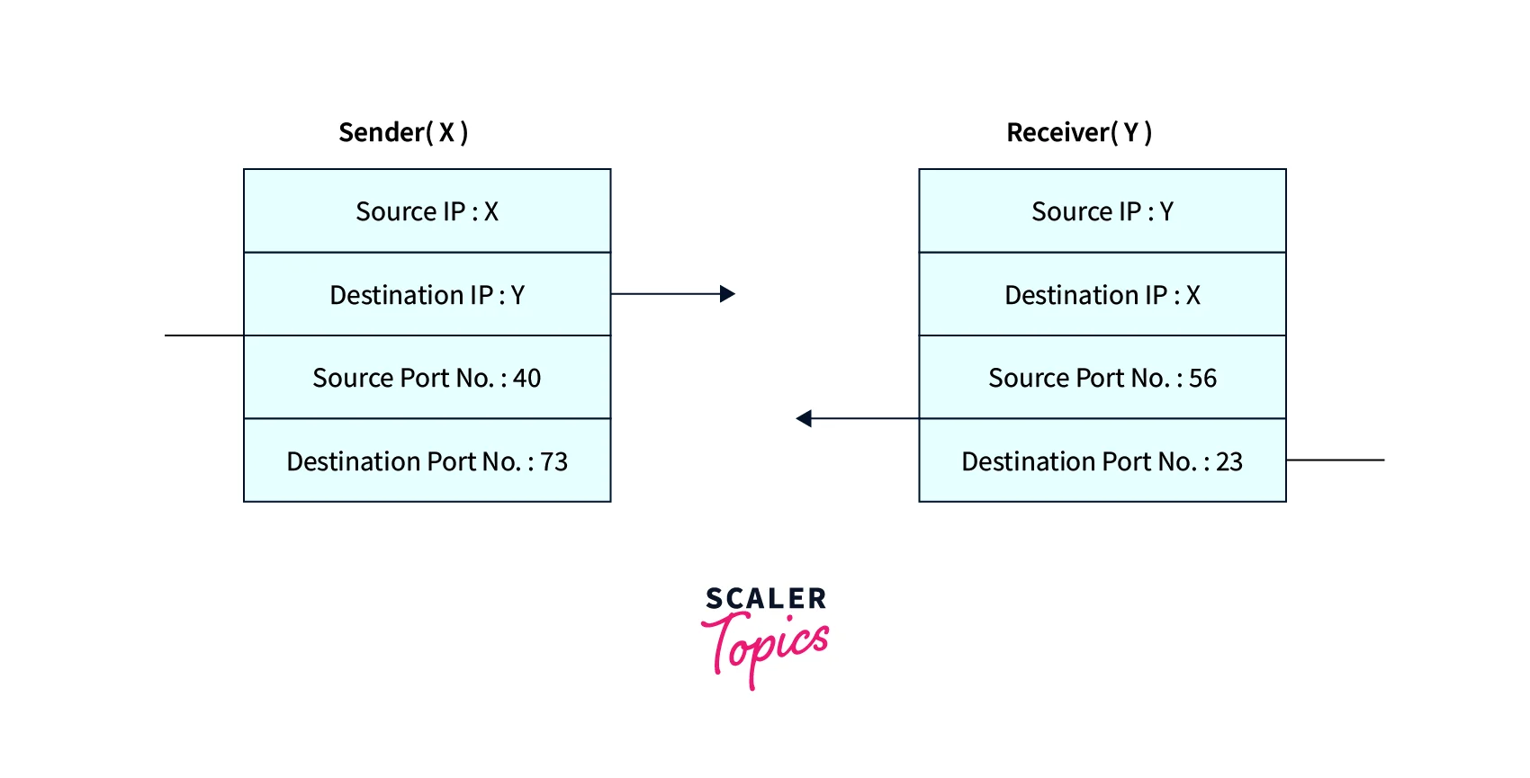
The sender must know the IP address of the destination and the port number of the application (on the destination side) to which he wants to transfer the data to send data from an application on the sender side to an application on the destination side.
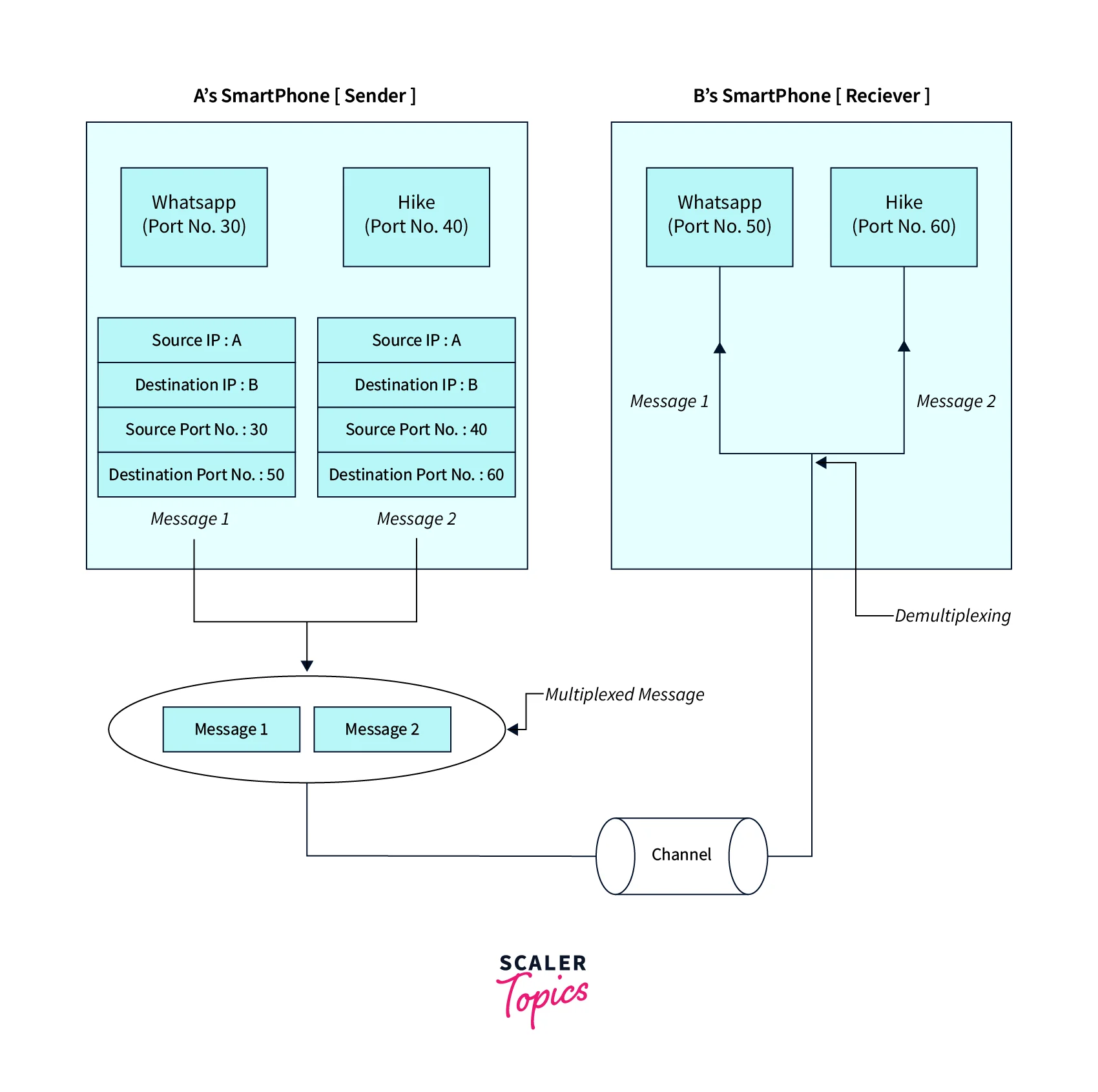
The following block diagram shows:
Take Hike and WhatsApp, two popular messaging services that are utilized nowadays. If A is the sender and B is the recipient, then both the sender and the recipient have these programs installed on their computers (say smartphones). Let’s say A wishes to communicate with B through WhatsApp and send them both a hike. A must provide B’s IP address and WhatsApp’s target port number when sending the message using the WhatsApp app to do this. The IP address of B and the message’s destination port number must also be included by A when sending the message in the latter scenario.
Now, the messages from both applications will be combined with the proper headers (source IP address, destination IP address, source port number, and destination port number) and delivered to the recipient as a single message. Multiplexing is the name of this procedure. The received message is unwrapped at the destination, and the individual messages (such as those from the hiking and WhatsApp applications) are forwarded to the relevant application by checking the destination’s port number. Demultiplexing is the name of this procedure. Similar to how A can get the communications from B.
Network Port
In computer networking, a port is a designation given to a connection endpoint to specifically identify it and guide data to a particular service. A port is a logical construct that identifies a particular process or a certain kind of network service at the software level, inside of an operating system. The port number, a 16-bit unsigned number, is used to identify a port for each transport protocol and address combination. Transmission Control Protocol (TCP) and User Datagram Protocol are the two transport protocols that employ port numbers most frequently (UDP).
Different ports are used to specify which protocol inbound communication should be routed to. They enable the operation of network services on a single host with a single IP address. Each port number corresponds to a different service, and each host is allowed a maximum of 65535 ports per IP address. The management of these ports’ usage is the responsibility of the Internet Assigned Numbers Authority (IANA). IANA divides ports into three types.
- Well-known ports or system ports range from
0to1023.
Can TCP and UDP Sockets Use the Same Port?
There is no connection between UDP and TCP ports. The TCP stack interprets TCP ports, whereas the UDP stack does so for UDP ports. Ports are a method of multiplexing the connection so that several devices can connect to a node.
As a result, higher-level protocols technically have the option of using the same or different TCP and UDP port numbers. On the other hand, a single machine can simultaneously interact with two distinct services utilizing the same port numbers for TCP and UDP.
Web servers, for instance, connect to TCP port 80. For convenience, the programs utilize the same port number for TCP and UDP. TCP and UDP ports are distinct, even if two programs connecting to the same port number could perform a comparable function. They are apart from one another.
Let’s use the example of a bank. Assume that TCP and UDP belong to separate banks. By convention, counter “maths” 1 is made as a reception by both TCP and UDP banks. They also put up counters 2 and 3 to process money.
As a result, both TCP and UDP bank clients can check in at counter “maths” 1. Furthermore, clients have a choice between counters 2 and 3 if they wish to deposit cash. The banks are completely distinct, despite the identical counter numbers. Furthermore, both banks are allowed to allocate their counters to various tasks at any moment.
TCP and UDP are hence unrelated, to put it briefly. To minimize misunderstanding, higher-level protocols may utilize the same port number by convention.
Conclusion
- While UDP is a connectionless protocol, TCP is a connection-oriented protocol. Speed is a fundamental distinction between TCP and UDP, with TCP being much slower than UDP. Overall, UDP is a lot quicker, easier, and more effective protocol, but only TCP allows for the retransmission of lost data packets.
- Since its nonexistent “acknowledgment”, UDP is faster than TCP because it can handle an ongoing packet stream. A resend is required for each negative acknowledgment where a data packet has been lost since a TCP connection constantly acknowledges a group of packets (regardless of whether the connection is completely stable or not).
- Multiplexing and Demultiplexing are two often employed technologies. A multiplexer (Mux) is a device used for multiplexing, whereas a demultiplexer is a device used for demultiplexing (Demux). A typical device nowadays will, however, be capable of both multiplexing and demultiplexing.
- The multiplexer and demultiplexer are combined circuits used in in-network transmission. An input is chosen from among numerous inputs by a multiplexer, and then it is broadcast as a single line. MUX or data selector are other names for the multiplexer. An input signal is multiplied by many by a demultiplexer. Demux or data distributor is the name given to it.
- The processes of transmitting data produced concurrently by several applications are referred to as multiplexing and demultiplexing. Each data segment is processed individually and transferred to the correct application in the destination system when the data reaches the Transport layer.