OSPF stands for Open Shortest Path First and it is an intradomain protocol. This protocol is used for exchanging information between the dynamic routers. OSPF protocol is based on the link state routing algorithm. OSPF is used within the autonomous system and it divides the autonomous system into different areas.
Introduction
- OSPF stands for Open Shortest Path First and it is an Interior Gateway Protocol which is mainly used for exchanging the routing information between the dynamic routers.
- It is generally used within the autonomous system of the Internet and used in large TCP/IP networks.
- In the corporate networks, OSPF replaced the old Routing Information Protocol.
- OSPF is one of the intradomain protocols. Intradomain protocol means that this protocol is used within the network or an area.
- OSPF protocol is the protocol that works based on the link state routing algorithm in which each router has the information about each domain and uses this information to determine the shortest path.
OSPF Areas
Refer to the below image to show the OSPF areas 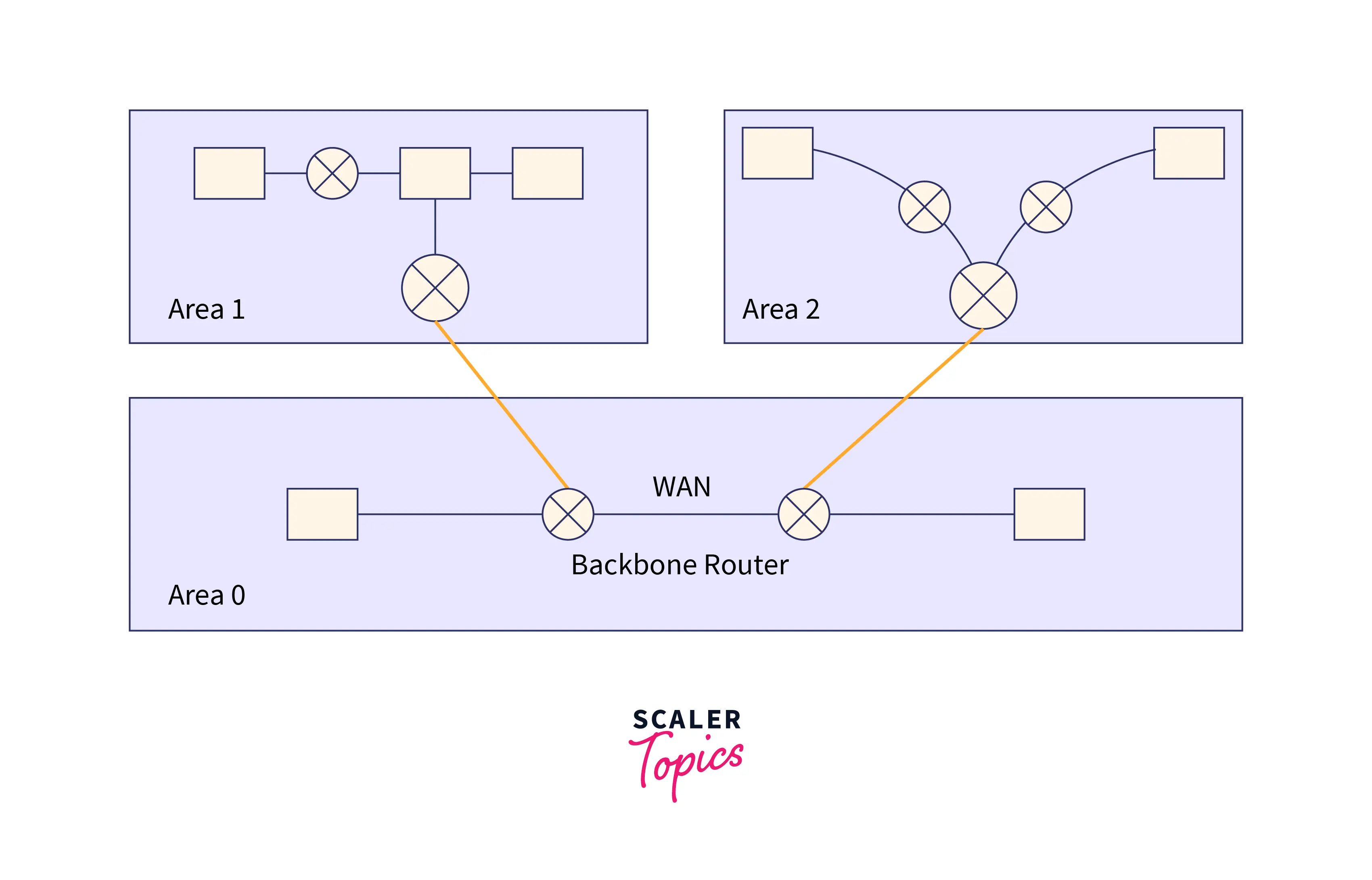 In OSPF, the Autonomous system is divided into areas to avoid the high traffic which is caused by flooding. These divided areas can be a collection of hosts, routers, and networks. As the internet is divided by internet service providers into various autonomous systems to make management easy, in this way OSPF divides the autonomous further into areas. Routers that are within the area are flooded with routing information.
Special routers are also there in a divided area. The routers that are present at the border of an area are considered special routers and these are also known as Area Border Routers. Special routers generally summarize the whole information of an area and also share information about an area with other areas.
Different divided areas of an autonomous system are connected to the backbone router. The main purpose of the backbone is to enable communication between the different divided areas
Working of OSPF
OSPF protocol working can be understood in the following three steps:
Step 1: The first step in the working of the OSPF protocol is to become the OSPF neighbors. The two routers that are running on the same link and are connected establish the neighbor relationship between them.
Step 2: Now the next step is to exchange the database information between the routers. When the router establishes the neighbor relationship they exchange the link-state database (LSDB) with each other.
Step 3: The third step in the working of the OSPF protocol is to select the best route. After an exchange of LSDB information, the router finds the best route for adding to the routing table.
How Does a Router Form a Neighbor Relationship?
Creating neighbor relationships is the first step in the working of the OSPF protocol. Before forming the relationship first thing is to select the router ID.
Router ID (RID) is a number that is used for the unique identification of each router on the network. In the IPv4 address format, there is a router ID. Router ID can be set in two ways. The first way of setting the router ID is to set it manually and the second way is that the router decides its ID on its own.
The logic used by the router to set the router ID is given below.
Manually assigned: First of all the router checks whether the router ID is assigned manually or not. If the ID is set manually, then that is considered the router ID. Otherwise, if the ID is not manually set then the router selects the highest ‘up’ status loopback interface IP address as an ID. In a situation, where no loopback interfaces are available then for the ID it will select the highest ‘up’ status non-loopback interface IP address.
Refer to the below image for a visualization of the manual assignment of the router ID 
Refer to the below image for a visualization of the manual assignment of the router ID 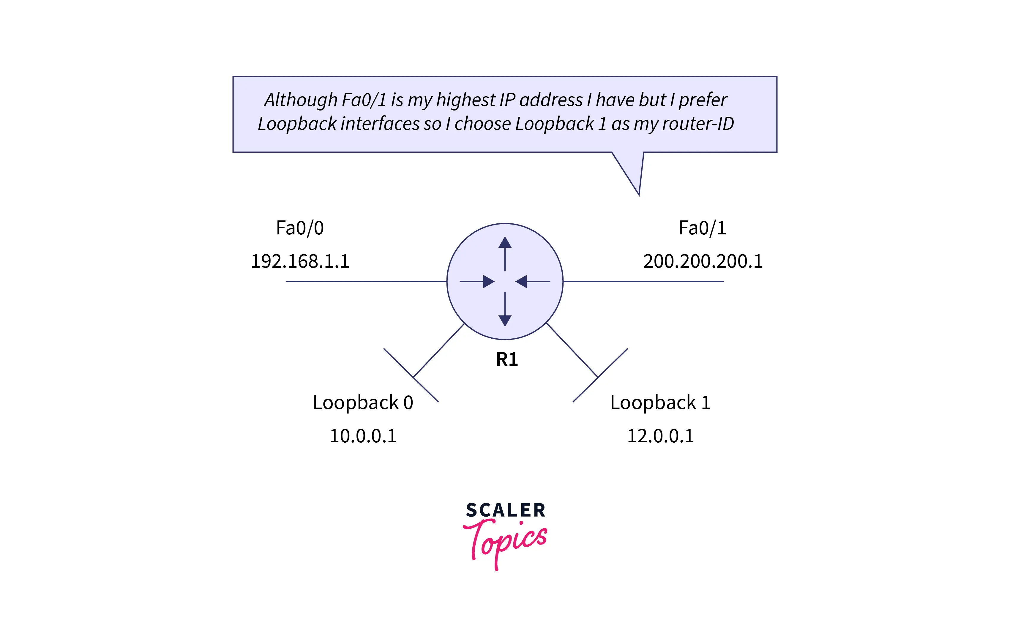
OSPF is used for providing communication between two routers that are connected using point-to-point links or numbers of routers that are connected. The two routers can be considered adjacent routers only when they exchange the HELLO message with each other. These two routers enter in a two-way state only when they both receive the acknowledgment of the HELLO message. The creation of relations between routers is allowed in the OSPF protocol as it is a link-state routing protocol. The two routers that have having same area ID, sharing their subnet, authentication, and timers will only be considered neighbors. Between routers, the relationship is created so that they can know each other. Between two routers if at least one of them is serving as designated routers as a backup designated router or connected using a point-to-point link then, only these two routers are considered neighbors in a particular network.
Types of Links in OSPF
Point-to-point link
When there is a direct connection between two routers without any host or router in between then it is known as a point-to-point link.
Transient link
In transient links, different routers are connected in a network. There are two ways through which a transient link can be implemented:
Unrealistic topology: Unrealistic topology is formed when all the routers in the network are connected.
Realistic topology: Realistic topology is formed when some designated routers are present in a network. A designated router is referred to as a router through which all the routers in a network are connected. It is mandatory for all the packets that are transmitted by the routers to pass through this designated router.
Stub Link
A Stub link is a type of network in which all routers are connected with a single router only. Through this single router only, data enters and leaves the network when needed using this single router.
Virtual Link
The administrator creates a virtual path between the routers when the link between these routers is destroyed. And this virtual link is a longer one also.
OSPF Message Format
Refer to the below image for the OSPF message format 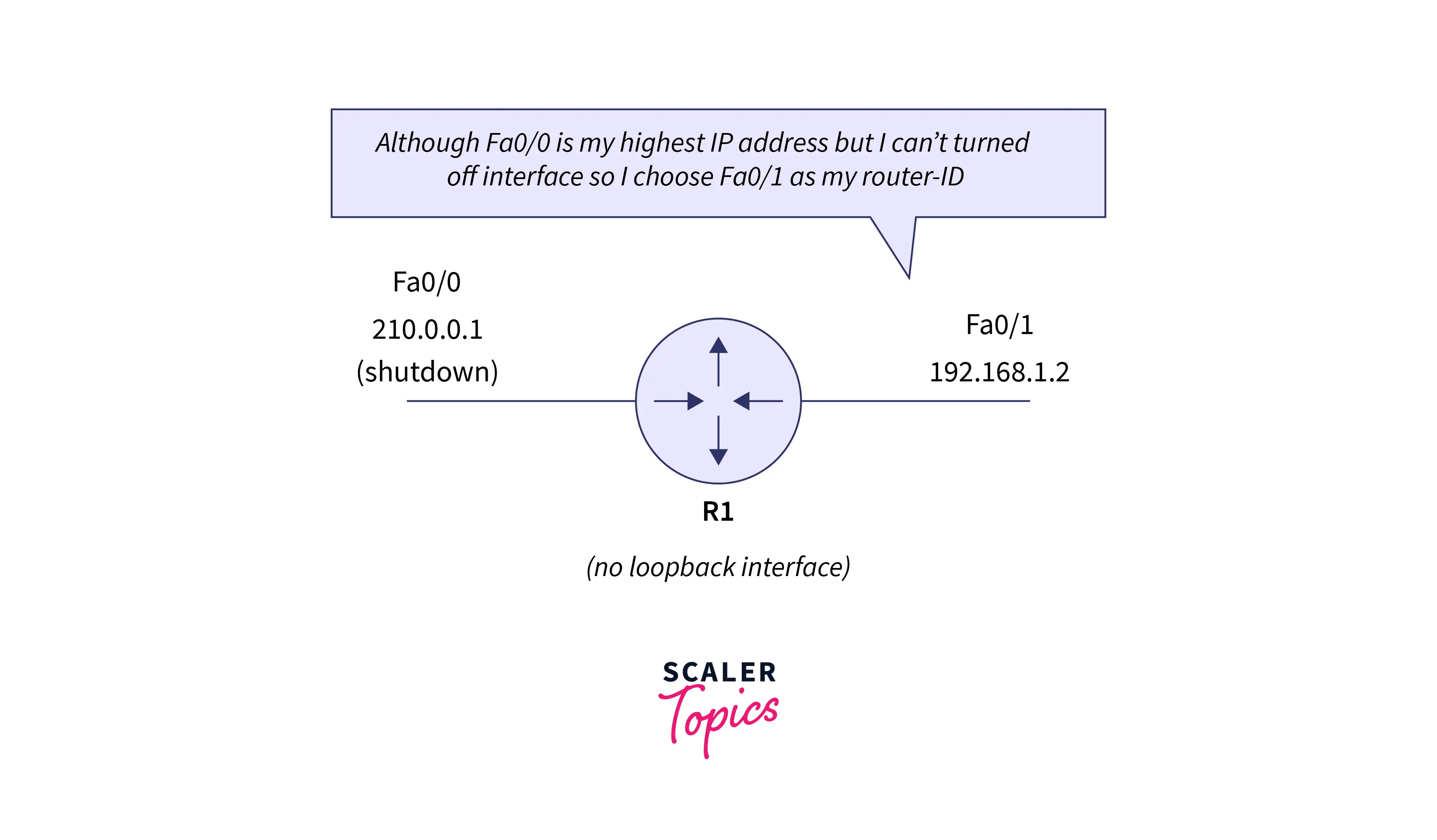
OSPF message format contains 8 fields which are given below: Version: It is the field of 8 bits that is used to specify the version of the OSPF protocol.
Type: It is the field of 8 bits that is used to specify the OSPF packet type.
Message: Message is a 16-bit field and is used to specify the total length of the message. The total length of the message also involves the header length. So the sum of the message and header length represents the total length.
Source IP address: It specifies the address of the source of the packet means the address from where the packet is sent to the receiver.
Area identification: It specifies the area in which the routing takes place.
Checksum: Checksum is used for specifying the data related to error detection and correction.
Authentication type: This field can contain two types of authentication i.e. 0 and 1. 0 specifies that no authentication is used, and 0 represents none. And 1 represents PWD and it specifies password-based authentication.
Authentication: Authentication is a field of 32-bit that specifies the authentication data’s actual value.
OSPF Packets
Hello
Hello packet is generally used for the creation of neighborhood relationships and to check the reachability of the neighbors. So HELLO packet is required at the time of connection establishments between the routers.
Database Description
After connection establishment, if the communication between the neighbor router and the system is happening the first time then the database information about the network topology is sent to the system from the router, and with the help of this information system can modify and update.
Link State Request
The router sends the link-state request to get the information about the specified route. Let us assume two routers are connected and router 1 wants to know the information of router 2. For this router1 sends the link state request to the router2. Router2 sends the link-state information to router 1 after receiving the link-state request from router 1.
Link State Update
Link state link-state update is used for advertising. Link state update is also used when the router wants to broadcast the link state.
Link State Acknowledgment
Link-state acknowledgment forces the router to send the acknowledgment on every link-state update and this increases the reliability of the routing. Let us understand it with an example, suppose router1 sends the link state update to router2 and router3. When router2 and router3 receive the link state update then in return they send a link-state acknowledgment to router1 so that router1 gets to know that router2 and router3 have received the link state update.
OSPF States
Down
When the state of the device is down, it is not able to receive the HELLO packet. This down state does not refer to the down condition of the device physically. It simply means that the process of the OSPF protocol has not been started.
Init
When the device enters in init state, it refers to the HELLO packet being received from the other routers.
Exstart
If the connection between both the routers starts, then the routers enter the Exstart state. In this state, the master and slave get selected based on the router’s ID. The main function of the master is to control the sequence of numbers and then begin the exchange process.
Exchange
When the device enters the exchange state, both routers start transferring the list of LSA(Link State Advertisements) to each other. The LSA includes a database description.
Loading
When the device enters the loading state, there is an exchange of the LSU(Link State Update), LSR(Link-State Routing), and LSA(Link State Advertisements).
Full
The device will enter into the full state if the exchange of LSA is completed successfully.
Router Attributes
Before entering the Extract state, the OSPF protocol selects one router that acts as a designated router(DR) and other routers act as a backup designated router(BDR). These routers are only the attributes but not the type of routers. If there is a condition of the broadcast network, then the router chooses one router that acts as a designated router and the other router acts as a backup designated router.
The selection of the designated and the backup designated routers is performed so that the number of adjacencies can be minimized and also to avoid flooding conditions in the network. They act as a central point where the routing information can be exchanged between the routers. Although there are point-to-point links that are directly connected, so a need for the selection of the DR (Designated Router) and BDR (Backup Designated Router).
If there is no selection of the DR and BDR, then the job of sending the update to all adjacent neighbors, which may lead to flooding is done by the router. The DR and BDR need to be selected for resolving the problem of flooding. Despite exchanging the updates among routers in the network, each non-DR and non-BDR transmits the updates to DR and BDR only. After that, DR divides the information of network topology among different routers in the same area. On the other hand, BDR acts as a substitute for DR. The routing information is also received by BDR from all other routers but BDR is not allowed to distribute that information. If the condition occurs when DR fails then, only BDR is allowed to distribute the information of routing.
The non-DR and non-BDR use 224.0.0.6 multicast addresses for transferring the routing information to DR and BDR. Then multicast address 224.0.0.6 receives routing information from the DR and BDR.
The DR and BDR can be selected based on the following rules:
- The router having the highest OSPF priority will be selected as DR.
- If there is a condition when no router has the highest priority then, the router having the highest router ID will be selected as DR. On the other hand, the router having the second-highest priority will be selected as BDR.
Let’s take this example to understand the complete concept of DR.
Refer to the below image for an example of the concept of the DR. 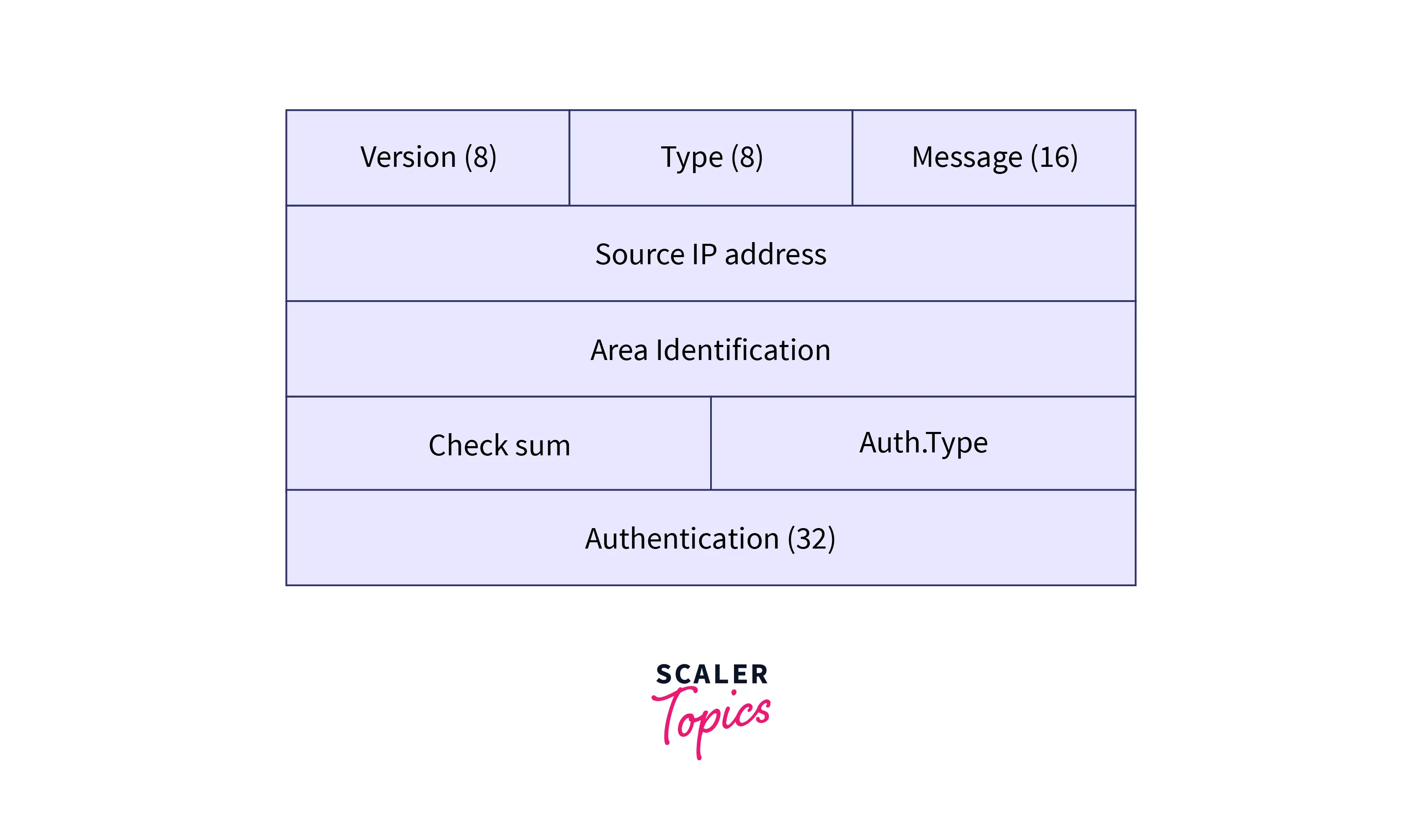
In the given figure, R1 will be selected as the DR as R1 has the highest router-id as compared to others and R2 works as the BDR as R2 has the second-highest priority among all. If there is a condition when a link fails between the system and R4 then, R4 updates about its link failure only to R1 and R4 respectively. After that, the DR will inform all the non-DRs and non-BDRs of this update. And also in this situation, only R3 is available and serves as a non-DR and non-BDR, except R4.
Conclusion
- OSPF stands for Open Shortest Path First and it is an intradomain protocol. This protocol is used for exchanging information between the dynamic routers.
- It is an Interior Gateway Protocol that is based on a link-state routing algorithm and used within the autonomous system.
- It divides the autonomous system into areas.
- Working on the OSPF protocol can be understood in three steps.
- The first step is creating a neighbor relationship and before establishing a relationship router chooses the router ID.
- Point-to-point link, Transient link, Stub link, and Virtual link are the different types of links in the OSPF protocol.
- The OSPF message format is divided into eight different fields.
- Hello, Database Description, Link state request, Link state update, and Link state Acknowledgment are the OSPF packets.
- There are six states in the OSPF protocol.
- Before entering the Extract state, OSPF selects one router that acts as a designated router (DR) and other routers act as a backup designated router (BDR).