For sending the packet to its destination we must be aware of the source MAC address and destination MAC address and source and destination IP address. The packet will be directly delivered if the destination is available in the same network otherwise the packet is sent to the default gateway first.
Introduction
For the successful delivery of the packet to its destination, we must know the source MAC address destination MAC address, and source and destination IP address. Below are some rules given for the packet flow in the network.
- The packet will be directly delivered to its destination host if the destination host is available within the network.
- The packet is sent to the default gateway and then the packet is sent to the destination host if the destination host is not within the network i.e. destination host is in a different network.
ARPmust be resolved if it is not resolved.- MAC address never crosses its broadcast domain.
IP Routing and Ethernet MAC Forwarding
The whole process of routing and forwarding is very similar. But, it becomes easier to learn the concept if we prefer to use IP Packet Routing at the network layer and Frame forwarding routing at the data link layer:
Concept of Network Layer Routing
It works based on the Dotted Decimal Notation Logical destination IP Address (172.16.10.20) which is present in the IP packet. So we can say that it doesn’t bother what either LAN or WAN use for connections like ATM, frame relay, fiber, etc. Its only work is to route the IP packets on the internet with the help of an address system
Forwarding Concept of Data Link Layer
In case ethernet is used, then it works based on a physical destination MAC address of 12– hex characters (3001.2222.2222). In other words, we can say that the ethernet physical address is used to transfer the packet until the IP packet does not reach its destination every Hop uses a different MAC address.
Routing IP Packets to Default Router
Refer to the below image for an example of packet flow in the different networks.
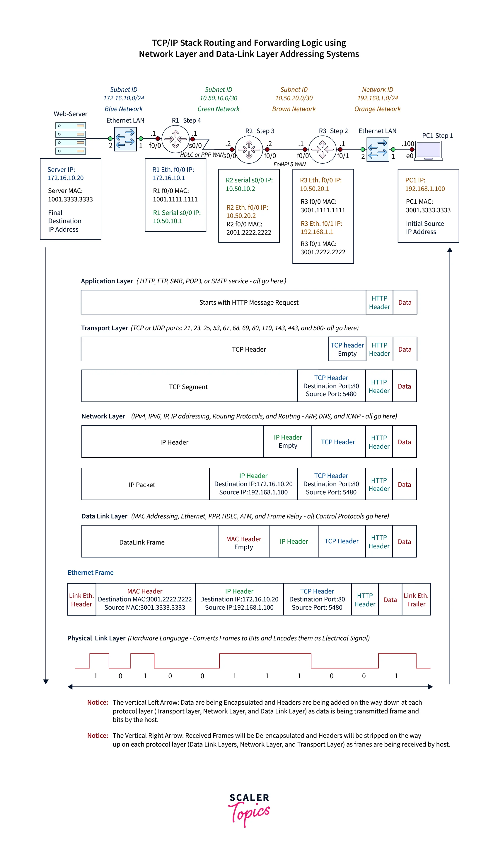
Suppose you are using PC1 and request a homepage of this website www.abc.com from a web server.
According to the above image-
The encapsulation process for the HTTP request is initiated by the IP/Stackof the PC1 is given below:
- The HTTP Data Request is encapsulated by the TCP/Stack of the application layer of the PC1 in the HTTP data header and after it, for other processing, handover to the transport layer.
- Now the further encapsulation process is done by the transport layer. It works to encapsulate the data header of HTTP into segments and add TCP ports of destination and source to the segment. After it handover these segments for further processing.
- Now the segment is encapsulated into an IP packet by the network layer and also adds the logical IP address of the destination and source to the packet. And after that handover this packet over to the data link layer for the framing process through the hardware addressing method.
- The IP packet is encapsulated into the frame by the data link layer. And add the MAC address of source and destination to the frame along with the ethernet trailer and header. And handover this frame to the physical layer for delivery process through ethernet standard or protocol.
- Now the frame is converted into a stream of bits by the physical layer but only one at a time. And after this these bit streams are encoded into signals according to the type of media ( wired or wireless ) used in a particular network and transmit these signals to the default gateway but only one at a time.
Forwarding Ethernet Frames to Default Router
While requesting a Home page abc.com from the server, the PC1 finds out that this home page is present at several subnets so PC1 selects the nearby router (R3) to transmit the packet.
The analysis process of the TCP/IP stack of PC1 was according to the destination IP address of the homepage abc.com and it was situated at a different number of subnets ( web-server 172.16.10.20). So TCP/IP of PC1 is selected to transmit the HTTP request to the nearby default router (R3) and it is present at the PC1 LAN.
To transfer the IP packet from PC 1 to R3, PC1, first of all, transmits the frame that has the IP packet. The MAC address of the R3 must be used by the frame that has an IP Packet so that it can reach the interface port of R3.
R3 Interface port received the IP packet and then with the help of a new MAC address, unpacked and repacked this IP packet and transmitted this again to the nearby router. This process will be continued to repeat till the IP address will not reach its final destination address.
Detailed Steps: IP Packet (s) Flow Across the Network
Step1: PC1 is Browsing for the Homepage of the Website abc.com
Downstream application layer: An application data or request is created and encapsulated with the required header of the application layer and for segmentation, it is sent to the transport layer.
In other words, in the HTTP header creation and encapsulation of HTTP request(GET message) by the application layer of PC1.
Downstream Transport Layer: Data sent by the application layer of the PC1 is received and encapsulated by the transport layer of the PC1 and it creates the segment(1) inside the TCP header and adds the port of the TCP(80) of the destination as the HTTP service receiver(2) and then it adds the port of the dynamic source(5480) as the Application(web browser) sender(3) and after that, it transmits the segments to the next layer i.e. network layer.
Downstream Network Layer: The UDP or TCP transmitted by the transport layer is received and encapsulated by the network layer in an Internet Protocol header and then it creates the IP packet and then it does conversion the domain name into their respective IP address with the help of DNS and then it also adds the IP address of the destination and the source into the packet and then this packet is routed to the Data-Link Layer by the network interface or NIC.
In other words, Inside the header of the IP, the TCP segment sent by the Transport layer is received and encapsulated by the network layer of the PC1 and then it creates the IP packet(1), and in the Ip packet it adds the IP address of the destination i.e. abc.com (172.16.10.20) as the final destination(2) and then it adds the address of the PC1(3) as the IP address of the sender (192.168.1.100) and then the IP packet is transmitted to the default gateway(R3)(4) by the help of the Data link layer by using the and then the IP packet is transmitted to the default gateway (R3) (4) by the help of the data link layer by using the NIC of the PC1 as the outgoing interface.
Data Link Layer Downstream with the help of NIC of Ethernet LAN: The IP packet sent by the network layer is received and encapsulated by the data-link layer of the PC1 inside the trailer and Header of an IP packet forming the frame(1) and then it uses the table of the ARP( Address Resolution Protocol) for adding the MAC address of the source and destination and it adds R3’s f0/1 LAN interface (3001.2222.2222) MAC destination address as the next-hop(2) and as the sender(3) it adds the MAC address of the PC1’s NIC source and then the frame is sent to the f0/1 of the RE by the using the NIC of the PC1 in the form of the outgoing interface by the help of the physical layer.
Downstream Physical Layer: Physical layer receives the data sent by the data link layer and converts it into the sequence of bits on the basis of the media type used like fiber, copper, or wireless it does bits encoding and in one time one signal is sent by the help of the media used to the outgoing interface or NIC of the device
Step 2: Upstream of the R3 with the Help of the LAN Port of the Ethernet
Physical Layer: The Signal sent by the physical layer of the PC1 is received by it with the help of the f0/1 interface of the R3 and after that, it does the decoding of every electrical signal into the streams of the bits(1) and then each bit stream is reassembled by it into the frame(2) and then every frame is sent to the data-link layer.
Data Link Layer: The frame sent by the physical layer is received by the data link layer and then in the received frame, the FCS(Frame Check Sequence) is applied on every received frame and then checks for the error if there is noerror(1) then it does the de-encapsulation of the contents of every frame(2) and the MAC address present in the trailer and header is discarded by it(3) and only the IP packet is forwarded towards the network layer(4).
Network Layer: It receives the data sent by the data link layer and the IP address of the source and destination is read (1) and then the IP address of the destination i.e. 172.16.10.20 is compared to the known IP subnets or routes by examining the entries available in the routing-table for finding the 172.16.10.20's subnet. After searching finally, the subnet is found at 172.16.10.0/24 and it includes the 172.16.10.1 IP address via the 172.16.10.254 (3) address.
Now the route stated after the routing decision is 172.16.10.0 through 10.50.20.2 and the f0/0 interface is used as the outgoing interface (4) and then the IP packet is transmitted with the help of the data-link layer and it uses the f0/0 interface for the outgoing interface.
Data-link Layer: Downstream of the R3 with the help of the ethernet of the WAN port: an IP packet sent by the network layer is received back by it and the encapsulation of this packet into the NEW Ethernet trailer and header and creates the new frame(1) and based on the cache table of the ARP it adds the MAC-address of R2 f0/0 (2001.2222.2222) as the new destination address(2) and as a sender, MAC-address of the f0/0 interface (3001.1111.1111) of the R3 is added as the new source address(3). And then the new frame is sent to the physical layer by using the f0/0 port of the R3 as the outgoing interface.
Physical Layer: New frames sent by the data link layer are received by the physical layer and then these frames are converted in the form of the bits(1) and then the encoding of the signal to the electrical signal(2) as here we are using a serial cable of the copper. One electrical signal is sent at a time with the help of the f0/0outgoing interface of the R3 by the EoMPLS link that is heading towards the R2(3).
Step 3: Upstream of the R2 with the Help of the Ethernet WAN Port
Physical Layer: Signal sent by the physical layer of the R3 is received by it with the help of the f0/0 interface of the R2 and then it does the decoding of every electrical signal into the stream of the bit(1) and then each but the stream is reassembled by it into the frame(2) and then every frame is sent to the data-link layer.
Data-link Layer: The frame sent by the physical layer is received by the data link layer and then in the received frame, the FCS(Frame Check Sequence) is applied on every received frame and then checks for the error if there is no error (1)then it does the de-encapsulation of the contents of every frame(2) and the MAC address present in the trailer and header is discarded by it (3) and only the IP packet is forwarded towards the network layer(4).
Network Layer: It receives the data sent by the data link layer and the IP address of the source and destination is read (1) and then the IP address of the destination i.e. 172.16.10.20 is compared to the known IP subnets or routes by the examining the entries available in the routing table for finding the 172.16.10.20's subnet. And after searching finally, the subnet is founded at 172.16.10.0/24 and it includes the 172.16.10.1 IP address via the 172.16.10.254(3) address.
Now the route stated after the routing decision is 172.16.10.0 through 10.50.10.2 and the s0/0 interface is used as the outgoing interface (4) and then the IP packet is transmitted with the help of the data link layer and it uses the s0/0 interface for the outgoing interface.
Data-link Layer: Downstream of the R2 by the help of the PPP Leased Line Serial Port: IP packet sent by the network layer is received back by it and it does the encapsulation of this packet into the NEW PPP or HDLC Trailer and Header and creates the new frame(1) And then the new frame is sent to the physical layer by using the s0/0 port of the R2 as the outgoing interface.
Physical Layer: New frames sent by the data link layer are received by the physical layer and then these frames are converted in the form of bits(1) and then the encoding of the signal to the electrical signal(2) as here we are using a serial cable of the copper. One electrical signal is sent at a time with the help of the s0/0 outgoing interface of the R2 by the EoMPLS link that is heading towards the R1(3).
Step 4: Upstream of the R1 with the Help of the PPP WAN Serial Port.
Physical Layer: The signal sent by the physical layer of the R2 is received by it with the help of the s0/0 interface of the R1 and then it does the decoding of every electrical signal into the stream of bits(1) and then each bit stream is reassembled by it into the frame(2) and then every frame is sent to the data link layer.
Data-link Layer: The frame sent by the physical layer is received by the data link layer and then in the received frame, the FCS(Frame Check Sequence) is applied on every received frame and then checks for the error if there is no error (1)then it does the de-encapsulation of the contents of every frame(2) and the MAC-address present in the trailer and header is discarded by it (3) and only the IP packet is forwarded towards the network layer(4).
Network Layer: It receives the data sent by the data link layer and reads the IP address of the source and destination (1) and then the IP address of the destination i.e. 172.16.10.20 is compared to the known IP subnets or routes by examining the entries available in the routing table for finding the 172.16.10.20's subnet. After searching finally the subnet is found at 172.16.10.0/24 and it includes the 172.16.10.1 IP address via the 172.16.10.254 (3) address.
Now route stated after the routing decision is 172.16.10.0 has the direct connection by utilizing the f0/0 interface as the outgoing interface (4) and then the IP packet is transmitted with the help of the data link layer and it uses the f0/0 interface for the outgoing interface.
Data-link Layer: Downstream of the R1 with the help of the ethernet of the LAN port: IP packet sent by the network layer is received back by it and the encapsulation of this packet into the NEW Ethernet trailer and header creates the new frame(1) and based on the cache table of the ARP it adds the MAC-address of the NIC of the web server (1001.3333.3333) as the new destination address(2) and as a sender, MAC-address of the f0/0 interface (1001.1111.1111) of the R1 is added as the new source address(3). Then the new frame is sent to the physical layer by using the f0/0 port of the R1 as the outgoing interface(4).
Physical Layer: New frames sent by the data link layer are received by the physical layer and then these frames are converted in the form of bits(1) and then the encoding of the signal to the electrical signal(2) as here we are using a serial cable of the copper. One electrical signal is sent at a time with the help of the f0/0 outgoing interface of the R1 by the LAN that is heading towards the web server(3).
Step 5: IP Packet Arrived at Its Final Destination
Physical layer of the web server: Signal sent by the physical layer of the R1 is received by it with the help of the f0/0 interface of the R1 and then it does the decoding of every electrical signal into the stream of the bits(1) and then each bit stream is reassembled by it into the frame(2) and then every frame is sent to the data link layer.
Data link layer of the web server: Frame sent by the physical layer is received by the data link layer and then in the received frame, FCS(Frame Check Sequence) is applied on every received frame and then checks for the error if there is no error (1)then it does the de-encapsulation of the contents of every frame(2) and the MAC-address present in the trailer and header is discarded by it (3) and only the IP packet is forwarded towards the network layer(4).
Network layer of the web server: It receives the data sent by the data link layer and the IP address of the source and destination is read (1) and then the IP address of the destination i.e. 172.16.10.20 is compared to its known IP address and it is founded that the destination IP address it matches with their IP address. so now finally packet has reached its final destination and now the de-encapsulation of the IP packet is done and the segment is transmitted to the upper layer i.e. sent to the transport layer.
Transport layer of the Web-Server: The segment sent by the network layer is received and de-encapsulated by the transport layer of the web server (1), and then there is an examination of the UDPor TCP ports of the destination of the segment (2), on the basis analysis done decision is made by the transport layer that this port is the type of the TCP port and it has number 80(3). Based on the decided port number data header is sent to the port 80 associated HTTP service and this HTP service is also responsible for providing the response and processing of the web pages.
Application layer of the web server: As it is meant to its port of the TCP i.e. 80 and it is found that the PC1 wants to view the website abc.com and has sent the GET message request so HTTP Service of the web server process the data.
So now the GET message has reached its final destination.
Conclusion
- For the successful delivery of the packet to its destination, we must know the source MAC address destination MAC address, and source and destination IP address.
- The whole process of routing and forwarding is very similar. But, it becomes easier to learn the concept if we prefer to use IP Packet Routing at the network layer and Frame forwarding routing at the data link layer.
- The packet will be directly delivered if the destination is available in the same network otherwise the packet is sent to the default gateway first.